Matchlock Design Question

Muzzleloading Forum

Help Support Muzzleloading Forum:

This site may earn a commission from merchant affiliate links, including eBay, Amazon, and others.

Zonie

Moderator Emeritus In Remembrance
MLF Supporter
Joined
Oct 4, 2003
Messages
33,409
Reaction score
8,572
Location
Phoenix, AZ
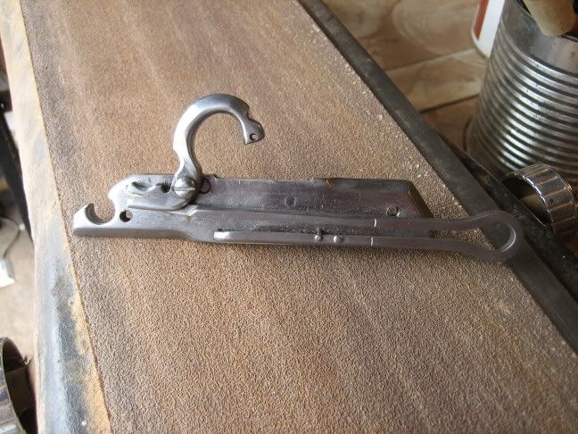
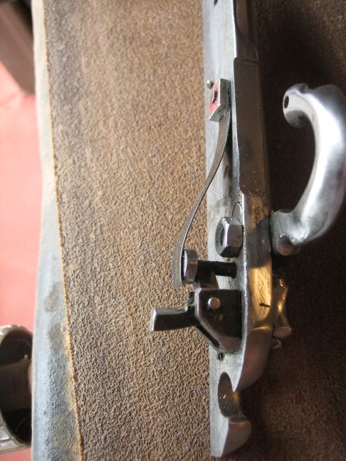
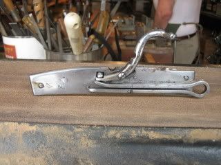
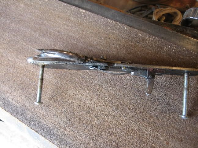
As an interesting thing to do in my retirement from designing jet engines, I'm designing a matchlock Lock which might be suitable for a Caliver and I have a question of you experts.

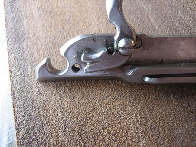
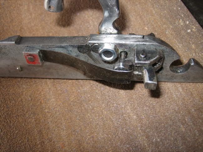
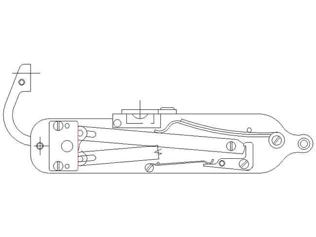
My current design has a spring loaded Serpintine which is released with a sear. The trigger would be a conventional design like a Flintlock uses.

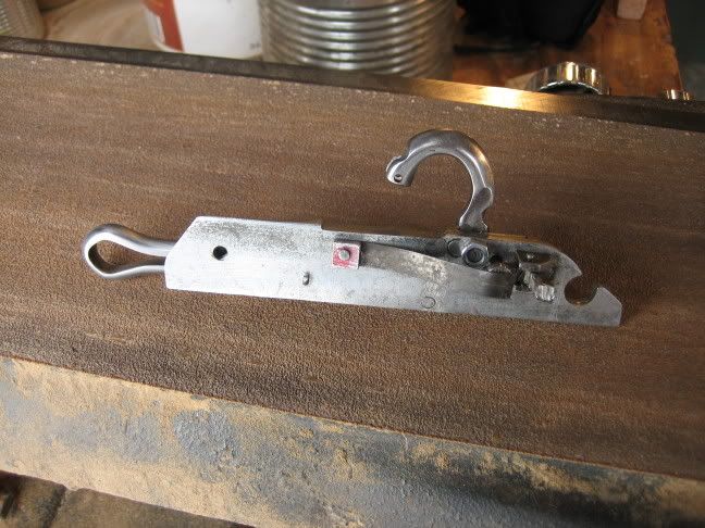
To fire a gun with this lock you would move the serpentine from the "fired" or down position to the cocked position where the sear would latch. Pulling the trigger would release the sear which would return the surpentine to the fired position using the internal spring.

The force to cock the lock would be about 2 pounds at the serpentines head.

This might be called a Snap-Matchlock?

Did such a Lock ever exist during the Matchlock era?
Any thoughts about this idea?

Zonie :)
 
There is such an animal as a snapping matchlock, but the mechanics are different. It sounds like you are using the tumbler and works of a standard cap or flint lock to do the duty of a snap lock.
Here's a post from 07/05 by benvenuto on the subject of snapping locks:
[url] http://www.muzzleloadingforum.com/fusionbb/showpost.php?post/144492/[/url]

This is the complete thread:
[url] http://www.muzzleloadingforum.com/fusionbb/showtopic.php?tid/144491[/url]

CP
 
Last edited by a moderator:
Hi Robin: I don't have any idea how much force it takes to snap the rope/serpintine down in a timely manner but I figured a 2 pound force would do the job.
Remembering that this force has to accelerate the rope and serpentine, is that too much?

Claypipe: Thanks for the link to the Matchlock post. I was happy to see that Snap type Matchlocks did exist. I would hate to design something original :grin:
No, the locks design is not using a tumbler like a Flintlock does.
I wanted 90 degrees of movement of the serpentine between the fired position and the cocked position and this much rotation would cause problems with the spring. It would almost create a need for the chain drive found in Wheellocks.

My design is based on the idea that this should be something that could be built at home without the need for fancy machines so chain drive doesn't fit the plan.

Just to help me keep the lock in a usable scale, I've sketched it's installation on a gun which is using a 24 inch 15/16 octagon barrel like would be found on a old used Traditions or CVA Hawken.

For your merryment, here is a picture of how things are going at the present time:
MATCHLOCK-1.jpg


Any thoughts about this lock and gunn layout are appreciated.
 
I only have one snapper here and it's not what you might call typical, two pounds just seemed like a lot :grin:

You have a French stock and a late pattern matchlock shape to the plate :hmm:

Either you are copying something or don't care a fig. Either sounds good to me :hatsoff:
 
Zonie,
I built my first chain for the TRS wheellock with cast parts I had to cut from the tailings tree clean up with file. I used only an electric drill and a vise. The three chains I made since with flat metal stock and left over bolt blank shafts of #4 size. I do now have a small drill press with press vice, but no fancy equipment. A chain is not difficult. :thumbsup:
God bless.
volatpluvia
 
Zonie, I agree with Leon. A chain is not difficult, just a tad tedious, but really satisfying when you have it completed. Kinda fun, too. So make a chain and see what you can come up with (and no matter what it is, I'll bet 2 pence that someone has already tried it long ago :haha: ) I use O1 drill rod for my pins. Good luck with your lock. Cheers, Bookie
 
Thanks Bookie, volatpluvia, Robin and Claypipe! :)

I'm sure my idea is not original, but it will not need a chain to transmit the spring load.
The mainspring will consist of a 2 leaf design which can be fabricated using standard .062 spring steel with simple bends, operating the rather typical bar which drives the serpentine shaft.

The main idea is to design something that can be made by a dummy like me without the need for any fancy tooling beyond an electric drill, some taps, drills, files and a propane torch.


Keep your comments/suggestions coming. :)
 
Mine has a coiled leaf spring in brass/bronze. That could be even easier than iron :thumbsup:
 
What about the rebounding idea to keep from snuffing out the match? Wasn't that the ultimate sophistication of the matchlock?
 
Rebounding? Don't look at me. I'm just a babe in the woods here.
To show just how much, I will ask, What is the diameter of the matches used in a Matchlock? If someone could give me a range of sizes it would help.
Thanks
Zonie.
 
Rebounding??? Never heard of that :hmm:

I think you have to put the rope in the pan and then wait for the bang. If the sidebast catches the rope you simply go and pick it up :rotf:
 
You may be thinking of the type of lock where the serpentine is held away from the pan by light spring pressure. When you apply pressure to the tricker, the match is lowered into the pan and when you release the tricker the serpentine returns to the rest position. It does rebound in a sense, but long after the vent blast has escaped.
 
Zonie: I went today and took some pics of a snapping matchlock lock made by my friend, George Silva. here is the front of the lock:

IMG_0976.jpg


The spring is a large cotter key

Here is the rear of the lock:

IMG_0977.jpg


This close-up of the dog shows the pin (directly behind the screw) that protrudes through the lock plate and holds the hammer in the cocked position.

IMG_0981.jpg


These are two close-up photos of the inner workings. There are only a few parts (spring, pin, L shaped lever that the trigger pushes against, and the grooved block that holds the L shaped piece.


IMG_0980.jpg


IMG_0979.jpg


:v
 
Here is another one (you can see that it has been well used)...

The L shaped pin itself has a teat that protrudes through the lock plate and holds the dog/ serpentine, eliminating the pin.

IMG_0982.jpg


Here is a rear view:

IMG_0983.jpg


:v
 
Nice pictures :applause: !How does the trigger engage in these Locks.The locks seem similar to the Japanese Teppo.
 
Thwe trigger pivots from a pin through the very top, as opposed to some sort of pivot pin in the middle of the trigger (like a caplock or flint). You simply pull on the trigger, which pushed the L shaped bracked backwards, allowing the dog/serpentine to drop.

These snapping matchlocks are based on Portuguese designs, hence their similarity to Teppos. :v
 
Very interesting locks!

After looking at these, and other pictures I suspect my design is perhaps a case of overdesign.
So far, not counting several pins and screws,I have 13 pieces :grin:. That includes the pan and pan cover.
My old boss always suspected that my designs were a little overdone. :rotf:
 
Speaking of over done, this is a barrels eye view of the lock.
MATCHLOCK.jpg

It is shown in the cocked position. The round circle on the horseshoe shaped sear block is a pin coming out of the paper towards you. A regular simple trigger would push up on it to release the bar which drives the serpentine crank.

At the top is a integral pan/pan cover block which sticks out the far side similar to a Flintlocks pan.

The box shaped item at the left is actually a cover plate which serves as a bridle and a retainer for the moving parts under it.

My gameplan is to silver solder the spring pins into slip fit holes and either screw or solder the pan to the lockplate.
The lockplate could be either brass or steel.
Zonie :)

The


Write your reply...
Back
Top