• Friends, our 2nd Amendment rights are always under attack and the NRA has been a constant for decades in helping fight that fight.

    We have partnered with the NRA to offer you a discount on membership and Muzzleloading Forum gets a small percentage too of each membership, so you are supporting both the NRA and us.

    Use this link to sign up please; https://membership.nra.org/recruiters/join/XR045103

TRS goodies are in!

Muzzleloading Forum

Help Support Muzzleloading Forum:

This site may earn a commission from merchant affiliate links, including eBay, Amazon, and others.

Erzulis boat

45 Cal.
Joined
Jul 14, 2005
Messages
566
Reaction score
78
Whoa...the snaphaunce lockplate is about the size of a machete, and the internals and external components are fantastic. This particular lock comes with instructions (backordered-not kidding).

The matchlock set has a cooling crack on the sear bar, but TRS immediately remedied the problem, and sent a new one.

The steel used for the casting appears to be a very quality alloy, it files very clean, and if I were to guess (I could ask, but mysteries are sometimes better)...it feels very similar to a low carbon alloy.

TRS treated me well, and have been answering the phone (I am not making this up).

First question.

The "jaw" of the serpentine on the matchlock, is it "split" then opened up? Is the barrel side of the split thicker (threaded side), or is the split down the middle? Any pics?
 
After my initial cursory inspection....

The matchlock caliver castings are not as straight or void free as the snaphaunce set. They are entirely satifactory, however. But, there is a difference.

The pivot shaft on the matchlock (serpentine) will be best served with a lathe or mill to establish a uniform cylindrical part, where as the snaphaunce will only require minor filing.

Both lockplates are very flat (!?). Of course, they must undergo additional "persuasion", but that is of no major concern.

The snaphaunce **** and pan are extremely straight and blemish free.

I am very exited to say the least.

TRS castings are not for the faint of heart, there is genuine work to be done. I would not want it any other way. :)
 
I have been warned to double check the hole templates against the smaller parts, as they sometimes forget to take into account part shrinkage. So measure twice, drill once?

CP
 
Thanks!

I am already looking at a lockplate notch on the matchlock pan that does not have a home on the lockplate.

The rear of the pan interface checks out, so it is the right pan, but there is something amiss for sure. :hmm:
 
EB,
That part about TRS parts not being for the faint at heart sure is true. My first look at the wheellock parts nearly convinced me that it couldn't be done. I am so glad I got help and got it done. It is quite an adventure. :bow:
God bless.
volatpluvia
 
E.B., if you have 1/2 the issues that Leon and I had with our wheelies, you'll be in pig heaven for sure. Do post photos as you go along. Cheers, Bookie
 
Picture024.jpg


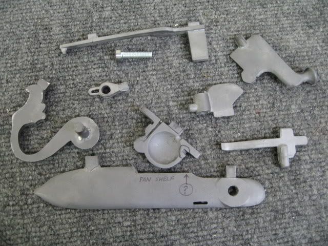
These are the matchlock castings. The quality of the castings is not top notch, and they will require mill work and some soldering.

I labeled the pan shelf on the lockplate, and as you can see, the front of the pan has the angled allocation for the plate. The lockplate shelf however, just runs on ahead forward without a proper receptacle. If the pan is installed as is, a very unsightly gap would be the result. It would appear that the builder made a mistake. I will have to modify the lockplate to allow a clean interface.
 
Got through to Jesse at TRS.

Answered all my questions in a jiffy.

The serpentine is split all the way down the "neck", and stops at the pivot area (rounded base). The split is centered.

The match cord tightening screw is threaded into the outer half of the "clamp", and the end going towards the barrel is "riveted" so to speak. It works just like a bench vise. If my explanation is lacking, I will post some pics soon.

The mystery notch in the front of the pan is due to part commonality. The pan in question is used for 2 different matchlocks. This pan is to be soldered onto the barrel, and the front notch is to be filed out.

The touchhole is to be 3/32" in diameter, and is NOT coned internally or externally.

Now it all makes perfect sense. :)
 
Erzulis boat said:
This pan is to be soldered onto the barrel

I think these are castings for the late type matchlock where the pan attaches to the lock plate, possibly by hook and screw :thumbsup:
 
I think that I may have fallen victim to a historical compromise of sorts.

This late matchlock should technically have a unitized pan/lockplate, but due to shared castings, TRS says to solder this one to the barrel, and eliminate the front groove.

I am considering making a new lockplate that allows this particular pan to be unitized with the lockplate, and secured via a rear screw. This might be the easiest route, as I would probably have to solder some additional metal to the pan to camouflage this discrepancy.

:hmm:
 
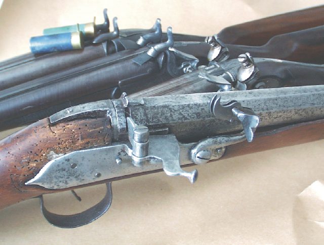
I have one of these locks fully assembled. The pan attaches to the lock plate with a single screw and a dovetail type notch that you will have to file or cut into the plate. The shallow groove on the top rear of the pan is where the flash shield sits. The shield is held in place by the same screw that the pan cover pivots on.
 
Did you drop the pan down lower than the uppermost rear portion of the plate? If so, was there any problem with articulation of the sear bar?
:confused:

The notch in question is the one I circled in the image, not the shield groove to the rear of the pan. If the pan is fully "dovetailed" into the plate (lowered) the sear bar will impact the pan even if it is trimmed. The pan cannot go any farther down on the lockplate without compromising the sear bar.

The above image shows that any front angled interface for the corresponding groove in the pan is absent. You might have a different lockplate. As posted before, this pan is a TRS compromise to allow commonality of castings, hence the "solder it to the barrel" advice given by TRS.
 
My lock plate does seem to have a bit more curve than yours, and it may be a touch wider, too. Otherwise they are quite similar. The notch on the front of the pan hooks onto the plate and the rear of the pan fastens to the lock plate with a screw. The serpentine is split down to within an inch or so of the pivot point.
 
Thanks Russ.

I will have to make a new lockplate, and modify the pan. This casting set is lacking in quality to put it mildly.
 
My lock is pretty crude. It has pits and irregularities all over it. Whether these imperfections came from the original that they pulled the molds from or the casting process I don't know.
 
I had assembled this same lock about three years ago, I know I soldered the pan to the plate and didn't have to make any parts to make it work. I will see if I can get the owner to remove the lock and get some pics of it inside and out for you. It may take a day or so, but hold off a bit and I'll get them posted. :thumbsup:
 
But, where do the bells and cuckoo bird go on it?

More seriously, that's a mighty fine looking set of castings and whoever runs that foundry sure knows what they're doing. Good luck on assembling it and getting it going.
 
I made a late pattern lock from plate with the integral pan and put it on a restocked 1640 barrel which had a fillet of metal hammered in where the pan used to be.

When I fired it, it blew apart in exactly the same way it did last time someone tried it :rotf:

not.jpg
 
Back
Top