• Friends, our 2nd Amendment rights are always under attack and the NRA has been a constant for decades in helping fight that fight.

    We have partnered with the NRA to offer you a discount on membership and Muzzleloading Forum gets a small percentage too of each membership, so you are supporting both the NRA and us.

    Use this link to sign up please; https://membership.nra.org/recruiters/join/XR045103

Under Hammers

Muzzleloading Forum

Help Support Muzzleloading Forum:

This site may earn a commission from merchant affiliate links, including eBay, Amazon, and others.
Joined
Jan 24, 2005
Messages
3,063
Reaction score
6,181
Location
New England, New South Wales, Australia.
Lifted this from the Percussion Forum. Anyone got any ideas on this as a percussionlock?
Like to hear some thoughts on just how the trigger works.
I see it as being at least two pieces and I think that I can see two pins.

What thoughts?
363348.jpg
 
CB,

the long bar over the top is the actal sear. If you study the pic, you can see its linked to the trigger. When the trigger is pulled the sar bar rotates and lifts up at the forward end. the mainspring and sear spring are just ahead of the trigger. The mainspring, I assume is pushing down on a hook, that is on the back of the hammer.

Really a sweet lil' piece of work!

Respect Always
Metalshaper
 
Thanks, I see all that, but what intrigues me is the actual trigger which seems to me to be in at least two pieces.
There looks to be a swell in the frame around the trigger and back of the trigger there appears to be a pin and also a pin in the trigger immediately under the frame as if the link to the sear is pivoted on the trigger.

I'm doing a drawing of a percussion version and if I can fathom out how to work the scanner I'll post it, otherwise I'll take a photo.

I think that this lock would be a nice one to build.
 
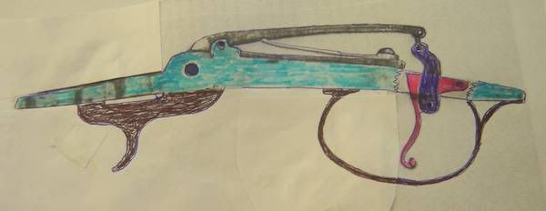
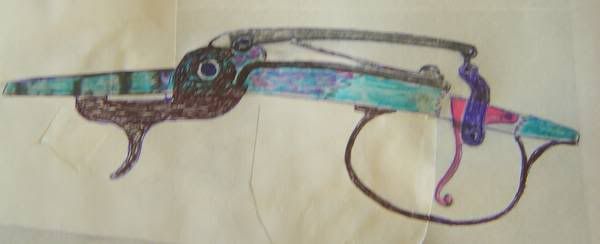
Without having the lock in my hands, it's just a guess but first I'll say I don't believe that there is a pin for a link on the back area of the trigger. If there were a pin or hinge joint at that location, and the large piece extending upwards thru the triggerplate towards the sear arm were itself a link, then I don't understand why there was a need for the small link connecting it at the top to the sear arm.

I believe the trigger and the material above the triggerplate is all one piece and it extends all the way thru the triggerplate up to the small link attaching it to the sear bar.
I also think the trigger extends back to some point behind the small pin that looks to be about 1/2 inch behind the trigger and is going thru the triggerplate. This, I believe, is the pivot for the trigger.
This arrangement will cause the trigger, the small upper link and the sear bar to rotate downwards when the trigger is pulled.
As the rear of the sear bar rotates downward, it pivots on the forward pin which raises the sear nose upward, away from the cocks half cock or full cock notch.

The "upper" blade of the spring forces the sear bar upwards causing the sear nose to engage the cocks notches. This movement raises the rear area of the sear arm which in effect, makes it the trigger spring.

Just a guess, but it works in my mind. :)
 
I was thinking the trigger and the dark blue section you have connected to it via a pin were one piece.
 
GMWW,

I agree, I've looked over the photo.. I've copied it into photshop and mucked about with it.. I think, what was beleived to be a pin is nothing more than a spot of corrosion or a scritch on the negative?
I see no reason to have the trigger in two pieces,when its linked and pivots independantly of the sear bar..

Nice picture of the percusiion version.. I Liked it!

But that is my opinion??

Respect Always
Metalshaper
 
I don't see any reason the cut and paste wouldn't work but if the blue piece is indeed seperate from the trigger, you could just do away with the top link and link the blue piece to the sear arm.
 
I tend to agree, why make extra work? But to my eyes there is a swelling in the body where the trigger goes through. The only reason I could think of for this is that the piece connecting to the scear arm is thicker than the trigger and fitted around it and extra space was needed to accomodate it.
 
Zoom in on the trigger, it is only one pc.

My question is the main spring on the hammer. I just don't see how it could have tension on the hammer, while setting on the cap. I suppose that the spring launches the hammer, then it just free wheels till it strikes the cap. It just doesn't look like it has enough travel to be in contact[the spring] with the hammer for the full ride to the cap? :hmm:
 
Colonial,

I'm not sure anyone has disputed the swell in the plate? I certainly agree that it is there. I think more than anything, they were trying to artisticly balance the look and feel of the plate?

The plate, at the front, would certaily have a large swell where the pan and frizzen are. To get away from < what I'll refer to here as> a Lollipop look.. a lil' decorative swell towards the rear would help the flow and cause your eye to see the whole thing.. eve if it 'is' tucked under the trigger guard?

Respect Always
Metalshaper
 
c161c53c.jpg


Thanks for the replies, there's nothing like talking a thing out.
Above, I've drawn in what I think the mainspring would probably be[url] like.In[/url] the first I simply left the spring where it was on half cock on the original flintlock.

I've been into the scrap box and found a suitable piece of steel, put a new blade in the hacksaw and tomorrow I'll roll up my sleeves... :grin:
 
Last edited by a moderator:
Colonial,

Your on the right track.. or at least the same one that I was headed down.. :hmm:

I invisioned the mainspring operation to be very similar.. I had thought the spring would follow a small channel, cut/milled into the inside of the plate.. that would help, in that the spring wouldn't have so much of an abrupt hook at its end.. and also allow it to have an arc to the arm.. in my mind :youcrazy: this would help give the hammer some extra speed/power??

Just trying to work out the details, for building up one of the flinters. Like you, I break out the files and hacksaws..

Respect Always
Metalshaper
 
I had anoher pic of the flintlock one and the spring did go down into the frame to rest on the sear face,belive it was a same lenght long "V" spring. Fred :hatsoff:
 
Here's a couple of Pics from Bruce Lingenfelter's site. It's a drawing of a stainless trigger / hammer assembly. I don't know if Bruce has actually made any of these or not. This hammer and trigger assembly looks like it could be made to slide into many different styles of underhammer rifles and pistols.

Underhammerstainlesstrggergrp.jpg


understainlessactionandtriggerpic.jpg
 
My that's a lot of drilling, Buy a Drill Doctor worth every penny!

I use to make my hammers for my matchlocks by drilling that way. If you wan't to ease life some, look at a Miwaukee Port-a-bandsaw. You could cut that lock in 5 mins. 300.00 well spent. You might also save some time by just forging it with a simple oxy/act torch. And filing/grinding to final shape. Your method works well though. Oh, I stumbled on drimels little endmill for slotting something like that, drill a couple holes and off you go.

Hope some of that helped

Looking forward to seeing the finished lock!

Pat
 
I agree about both. Thats alot of holes. And the drill doctors are great. please dont stop showing progress on this project. I am also trying to build a under hammer and would very much like to see how you do it. Ive totally trashed one so far, started over today on the second try. round 2 ding ding
 
Back
Top