• Friends, our 2nd Amendment rights are always under attack and the NRA has been a constant for decades in helping fight that fight.

    We have partnered with the NRA to offer you a discount on membership and Muzzleloading Forum gets a small percentage too of each membership, so you are supporting both the NRA and us.

    Use this link to sign up please; https://membership.nra.org/recruiters/join/XR045103

First Build!

Muzzleloading Forum

Help Support Muzzleloading Forum:

This site may earn a commission from merchant affiliate links, including eBay, Amazon, and others.
time to ' 'fess up... ' I tried the long drill gadget from Track when I built my first stock from a blank.

it was a disaster. wouldn't cut, wouldn't take an edge, wouldn't keep the edge...

finally I got a fellow who does body work down the road a bit to spot weld a drill bit onto a bit of rod. this worked great.

I did, however, have plenty of 'guides' and I used a brace ... sometimes it's best to leave the power tools unplugged.

good luck with the build ... keep the pictures coming!

:thumbsup:
 
I agree. The bit is not sharp, and I should have spent more time trying to make it so. For what they cost, I was expecting more as far as the cutting surface. My experience with drilling wood is that a brad point bit should be used, especially when drilling end grain. If anyone knows of a machine shop that can attach bits to rod stock please let me know! I thought I could get it done here at work, but I was mistaken :(
 
what my friend did, if memory serves, was to grab a hunk of one inch angle iron (it was about four feet long) ... about five inches from the end, he cut out a portion of the middle, so the sides were still there, but the area where the angle was had been removed ... then he clamped the rod into the angle, so the squared up end of the rod was exposed by the hole .. he butted the drill bit up against the rod, clamped it down, and tack welded the two together ... a quick pass with a hand grinder took down the weld which was bigger than the diameter of the drill bit, and there we go ...

sound pretty jimmy- rigged, but it worked great.

good luck with your build, and send more pictures!

:wink:
 
Update:
My first attempt at routing the belly patch channel did not go well. Knowing better, but doing it anyway, I just clamped a straight edge to the gun and routed. There was hardly anything to clamp to since the gun is so thin, and of course, the board moved and my cut drifted about 1/16 of an inch:
Bad - :td:
IMG_1123.jpg

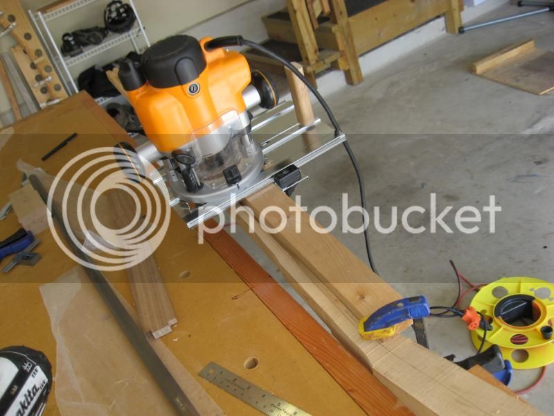
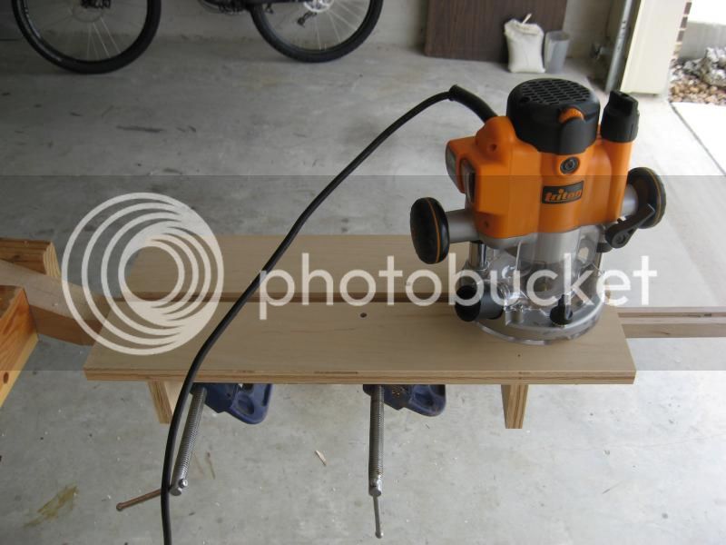
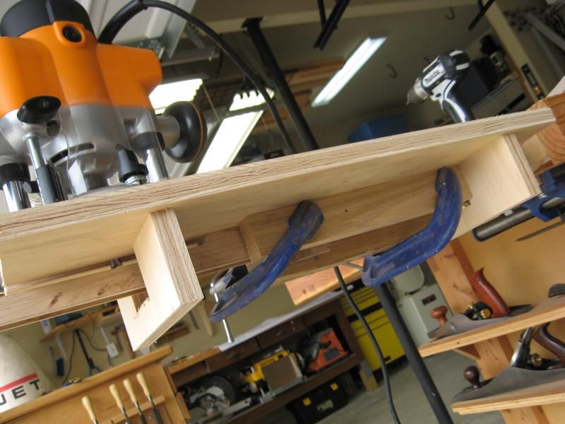
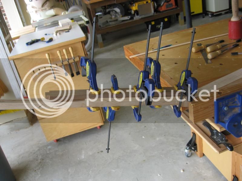
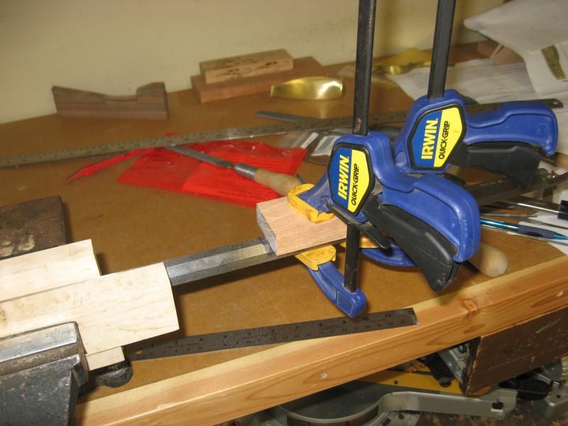
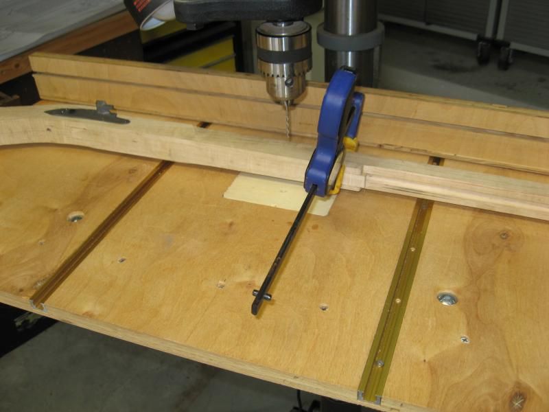
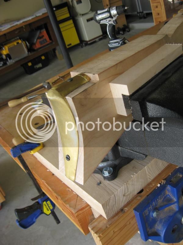
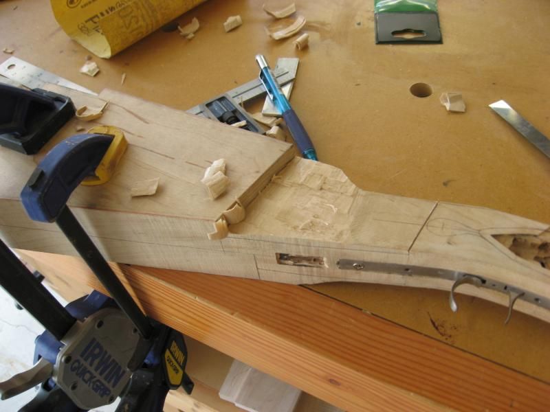
Disgusted with myself, I had to do a little thinking and came up with what I thought was a clever jig. First I put a 5/8 template bushing on the router with a 1/2" spiral upcut bit. For this type of set up you need two parallel guides, so I determined how wide to space my guides and attached them to two spanners. I cut out grooves in the spanners for the gun to sit. Then I clamped two pieces of scrap to the gun and screwd the jig to the scrap. ROCK SOLID!!! :grin:
Top:
IMG_1126.jpg

Bottom:
IMG_1127.jpg

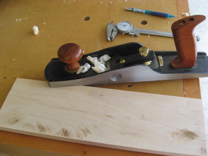
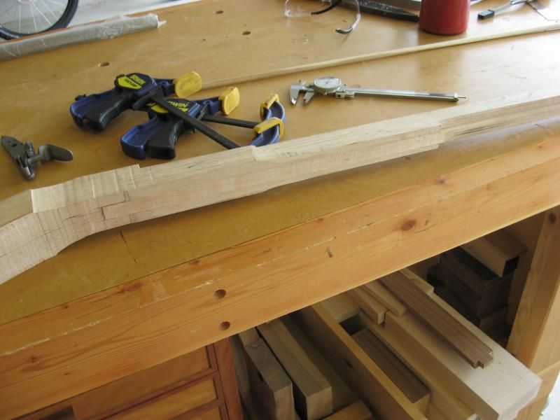
Once the groove was routed, I cut an oversized patch with the table saw and brought it down to size using my super duper Veritas low angle plane. If you do not own one of these, I highly recommend getting one. I can take shavings from 1/1000" to as large as I can handle.
IMG_1128.jpg

Once fitted, I routed a groove in the patch using a box core bit. This eliminates the need to re-drill (I hope).
Gluing in patch with Titebond III:
IMG_1129.jpg

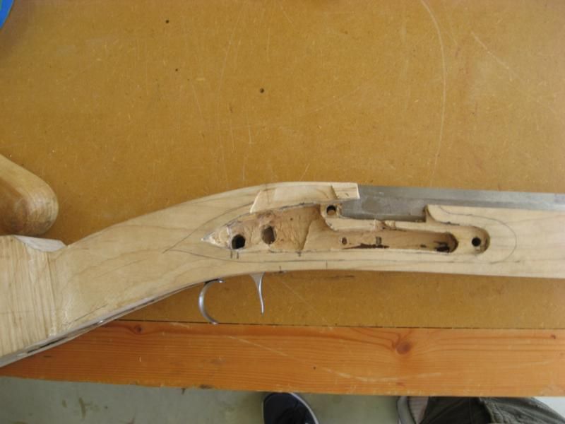
Final product. Besides the wood not matching, it looks pretty good! Note to self - save scraps until project is complete:
IMG_1132.jpg

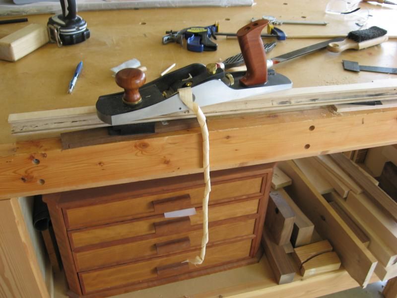
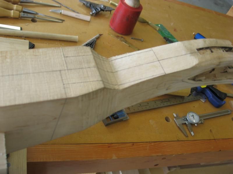
Next step, reduce side thickness from muzzle to panels to 1/8" using the plane. Did I mention I love this plane?
IMG_1133.jpg

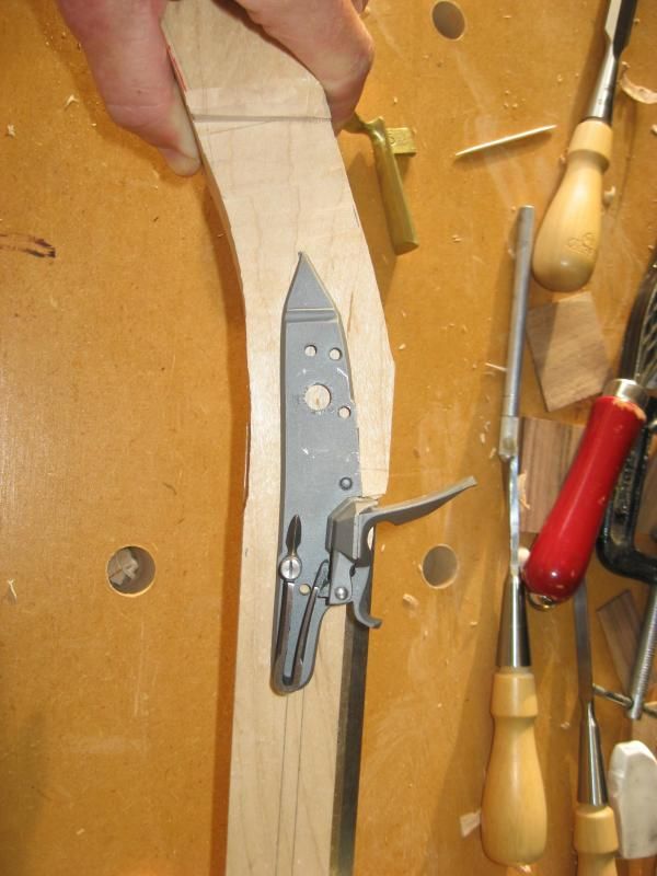
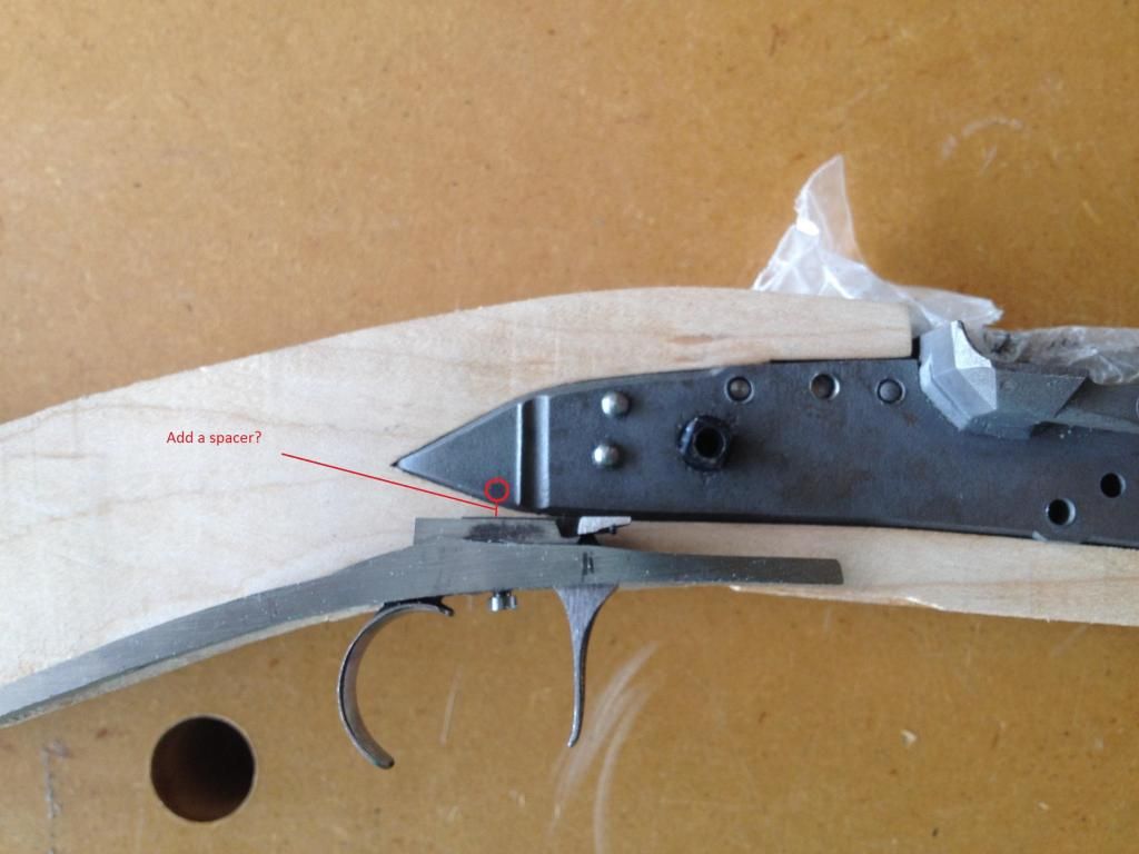
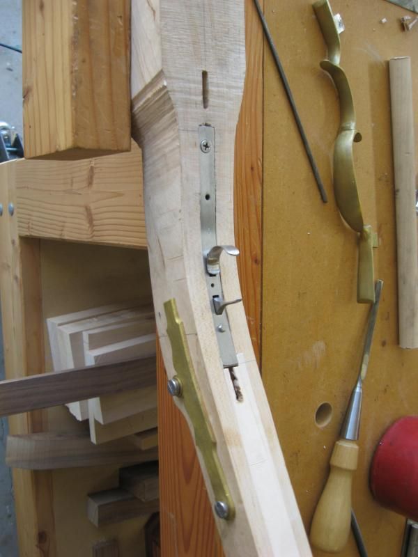
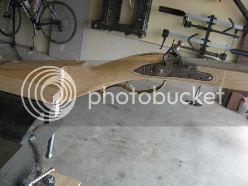
I reduced the panel thickness to the depth of the bolster, then marked the touch hole, 1/8" in front of breech plug, located the lock with the front centered on the web, the rear centered on the wrist, and the pan centered on the touchhole. For some reason I can't rotate this picture:
IMG_1135-1.jpg

If anyone see's anything way off, please let me know. I plan on inletting the panel tonight, after I taper the sides.

Thanks!
 
fair recovery on the RamRod hole whoopsie ... good luck with the inlet.

(nice plane, by the way ... been meaning to get one, and now I'm better motivated)
 
Update - first thing I learned is to buy a main spring removal tool. Although I took it off several times with channel locks, I managed to snap it. :cursing: Now, $50 later I've got a new spring and tool on the way. So, I almost have the entire lock with guts inletted, but now seem to have a problem with trigger placement. As you can see in the picture below, the sear is located where the circle is, and my trigger bar (if that's what it's called) seems to be too low.
Lock2.jpg

Once again I can't seem to rotate the picture. :idunno:
So that leaves two options, or really one, as I see it. Add a spacer to the trigger (by silver soldering?), or reduce the depth of the belly. The belly option is out since I've only got about 1/16 of wood underneath the ramrod channel. So, my question is, how would the veteran's handle this? Any help you can provide is much appreciated!

Thanks!
 
Hi,
I hope you are working from drawings because they do help you avoid these kinds of discoveries. That said, there is no problem with your configuration as it is with respect to firing the gun with the triggers set. The rear trigger bar will spring up and hit the lock sear firing the gun. The problem is if you want to fire the rifle without setting the triggers. In that case you will have a lot of travel in the front trigger before it engages the lock sear. You can solder a blade extension, which will work. I would first make the piece, harden it, and then solder it on with low-temp silver solder like Brownell's Hi-Force 44, and then grind to shape. You can also dovetail the bar extension in and then solder but to do so requires you to anneal the trigger so it can be cut. The other solution is a different set of triggers with higher trigger bars, which you can easily obtain and save the current set for your next gun (or sell them). A third option is to make a new front trigger. It isn't hard just using a piece of medium carbon steel, hacksaw, files, hammer and a torch.

dave
 
In whatever you decide to do, make sure that sear has enough room to travel when cocking the hammer. It's one of those things I've had to spend a good bit of time experimenting on. I like my double set triggers to function set or not...and not have much play if not set - just a thought. I spent a good bit of time on my triggers with my current build.
 
Hi Dave,

Thanks for the advice. I like the idea of soldering on a trigger extension. To answer your question about plans, my answer is...sorta. I'm referring to them here and there but am sort of winging it, which explains how I got here in the first place :grin: I'm a slow learner, but now I know what to do, so full speed ahead!

Thanks again
 
Wrong.

Half speed ahead or less is the correct answer.

Full speed will get a builder in all sorts of difficulties. :wink:
 
Update:

Cut my dovetails for barrel lugs. I cheat. I need a wooden block to guide my cuts. Ain't gots the skilz to freehand:
IMG_1143.jpg

Pinned barrel in:
IMG_1145.jpg

My little tool for drilling the tang bolt:
IMG_1146.jpg

Tang bolt and trigger plate in. I know I made some goofs here. It is my understanding now that the trigger plate should be trimmed ahead of the tang bolt. We'll do that on the next gun :grin:
IMG_1147.jpg

Side view of lock mortise:
IMG_1148.jpg

Butt plate installed. I also got me a new vice. WOOOHOO! Ergonomics you know...this one is at the proper height :grin: I made a big beefy base, and then clamp it to my wood vice. SWEET!!
IMG_1153.jpg

Laying out the wrist:
IMG_1154.jpg

Chiselin' out a little wood:
IMG_1156.jpg

Preliminary shaping. I also made shallow mortises for the trigger guard, drilled, and pinned it. the This is where I am today. I think it's turning out alright so far!
IMG_1160.jpg


Starting to look like a gun. Very exciting!
 
Doing good!
One bought, looks as if the tang needs a small undercut, the bent more....you can start that tang curve right at the breach....that will thin the wrist.

And dang you.....I had to add to my lee valley wish list....that low angle plane looks to be wonderful.....and I need a Stanley #50.....with all the blades, and a few custom ones.... :doh:

Those planes could replace that bad bad router...... :nono:
Marc
 
Hi,
You are doing pretty well but you made a mistake installing the trigger guard and pinning it at this early stage. Don't put the trigger guard in, cut lock panels, inlet toe plates, or patch boxes until the gun is almost to its finished shape, ready for final smoothing or sanding. That is because, you will inevitably need to adjust the architecture of the gun as you go, particularly since you are not really using any drawings.

dave
 
Yup.

The breach has a hump to it. The only way to get it right is with a file or grinder or milling machine That will thin out the wrist some too, but will change the tangent angle of the tang bolt, and give you a bolt that will be a little proud on (probably) the back edge. That's why you should wait to drill the tang bolt until after the final wrist shape is determined; so that the perfect location for the tang bolt is achieved.

That will also help you with your comb line. From what I've observed in Lancasters, is that the comb line (if extended) should almost perfectly intersect the tangent of the curve of the barrel / plug turn.

If you look at Jaegers, their comb line intersects further down the wrist. Same thing with more modern guns, where it's almost parallel in the cheek piece. (In some modern heavy caliber guns and target guns it actually slopes downward.) A rising comb line contributes to these guns having a bit of a reputation as "cheek slappers" but that's how they were made.
 
Thanks to all for the advice. I'll see what I can do about removing the hump from the tang. If it's going to affect the angle of the tang screw dangle too much, I'll take off what I can and leave well enough alone :grin:

Thanks again for all the help!
 
Well,the tang can be filed, but that leaves it kinda thin....the method I prefer is to cut the under part of the tang toward the plug....then get her bent more....then lightly file the joint smooth gentle curve....all the while deepen your inlet for it...it will lengthen it a tad..... :hmm:
It will affect the head of the screw some, but that might be filed too....but it ain't bad......

Maybe just leave well enough alone here.....we may be straining at gnats, and swallowing camels :doh: :rotf: :rotf:
Madmanmarc
 
kaintuck said:
Maybe just leave well enough alone here.....we may be straining at gnats, and swallowing camels
Madmanmarc

Great expression! When we work on these things, as we are working, our world consists of a tiny little area, 1/4" x 1/4", sometimes smaller. It's easy to forget the 5 foot rule at times.
 
Back
Top