• Friends, our 2nd Amendment rights are always under attack and the NRA has been a constant for decades in helping fight that fight.

    We have partnered with the NRA to offer you a discount on membership and Muzzleloading Forum gets a small percentage too of each membership, so you are supporting both the NRA and us.

    Use this link to sign up please; https://membership.nra.org/recruiters/join/XR045103

Making a 1770s British Rifled Officer's Fusil

Muzzleloading Forum

Help Support Muzzleloading Forum:

This site may earn a commission from merchant affiliate links, including eBay, Amazon, and others.
Joined
Nov 26, 2005
Messages
5,212
Reaction score
10,832
Hi,

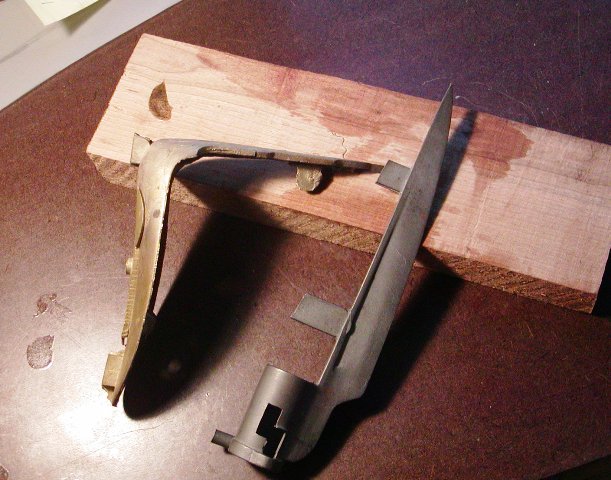
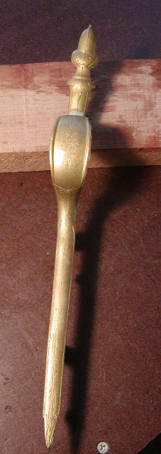
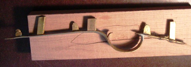
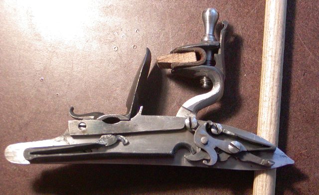
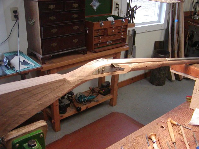
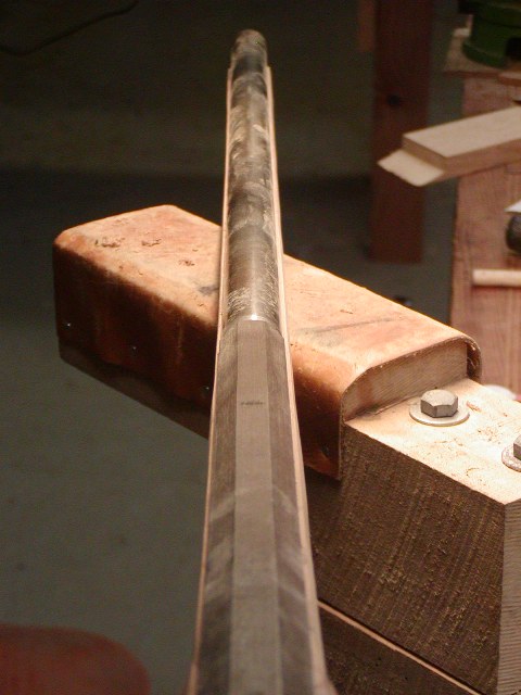
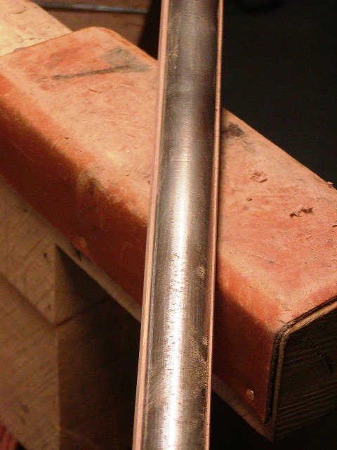
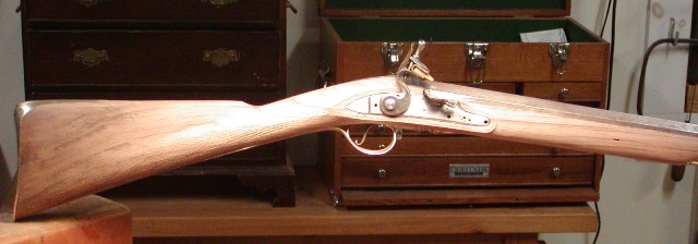
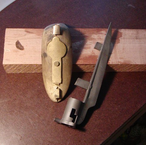
Well here I go again. I have 3 projects going on at the moment, Josh's rifle, a pattern 1730 Brown Bess and a 1770s rifled officer's fusil. I've wanted to build the rifled fusil for a long time and Chris Laubach sold me the perfect barrel and stock for it. I had TRS parts for a Twigg fusil including the buttplate, triggerguard, and parts set for the lock. There were not many rifled fusils made by the British in the 18th century but Bailey shows examples by John Hirst and John Twigg in his book on British military flintlock rifles. So I am making a rifle based on examples by those makers. Fusil just means "gun" in French. In the English military context it meant flintlock guns issued to "fusiliers", which were units tasked with defending artillery. The flintlocks were safer around the powder for cannons than infantry with matchlocks and burning match cord. As such, it had no implication of style or bore. Flintlock muskets issued to fusilier units were fusils. Later it tended to be confused with carbines, which were lighter, shorter, and of smaller bore than muskets. But "fusil" technically was not associated with any official military specification. So officer's fusils, which were usually smaller and lighter guns than muskets, really just meant guns carried by officers. There was no official pattern and most were purchased privately by the officer or regiment.
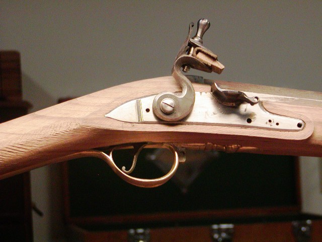
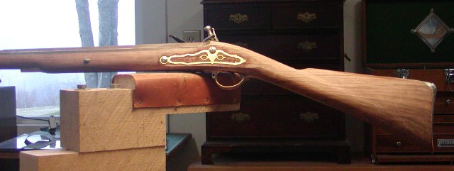
My project is based on guns by John Twigg and John Hirst during the 1770s. As such, it looks like a 1770s fowler with rifled barrel and fitted with a short bayonet that is stored in the butt. The acorn trigger guard is correct for this period and there will be the coarse checkering on the wrist that began to be fashionable in the 1770s.
5Mqu60G.jpg

7QdTDT3.jpg

DfKZ5lJ.jpg

4r4THxq.jpg

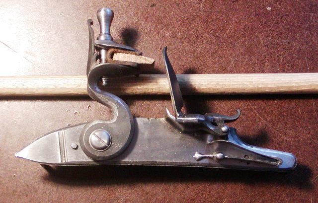
In addition, the lock is flat-faced as it should be. In the 1770s only livery, military, and cheap trade guns had round-faced locks. I built it from TRS castings but replaced the cock with one from a Chambers early Ketland lock, which has much better geometry. I will cut the proper two-stepped molding around it later.
fWEw2KL.jpg

YPcy7Ql.jpg

The barrel is a Colerain "D" weight octagon to round 42" inches long and 0.62 caliber. I cut it back to 39", which improved the balance immensely. It has to be fit for the bayonet. The stock is English walnut, which Chris had the barrel inlet and 3/8" ramrod groove and hole already done. The thicker ramrod will be fine for a rifled gun and I am taking measures to keep the gun really slim despite the thickness of the rod. The hardware will be brass and I will cast the side plate, which will be a panoply of arms. I will also create a wrist escutcheon.
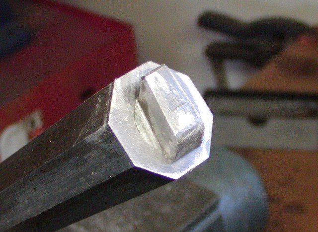
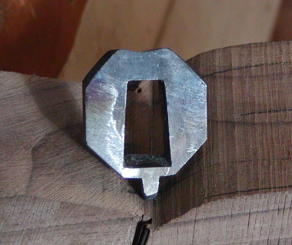
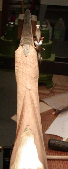
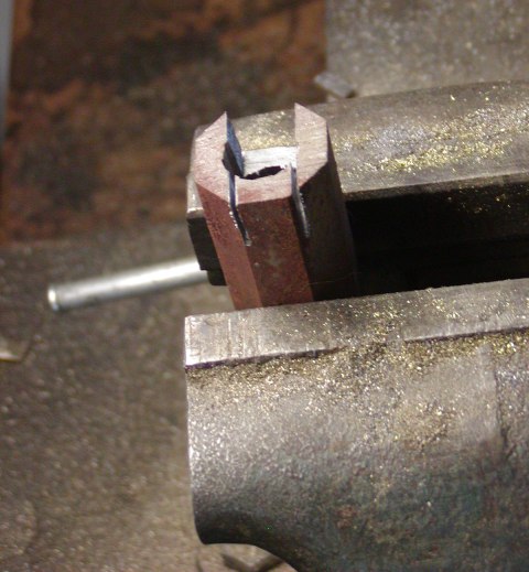
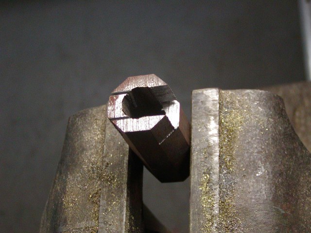
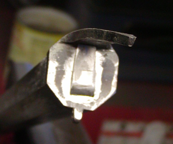
The standing breech is from TRS and I filed the breech plug fitted to the barrel into a hook for the breech. Note that it tapers toward the top. That provides a nice snug fit. Also note the lug on the bottom for the cross pin, an essential feature.
UiSaY6E.jpg

l1eFcl9.jpg

yHtWAZs.jpg

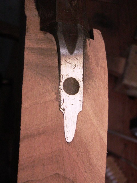
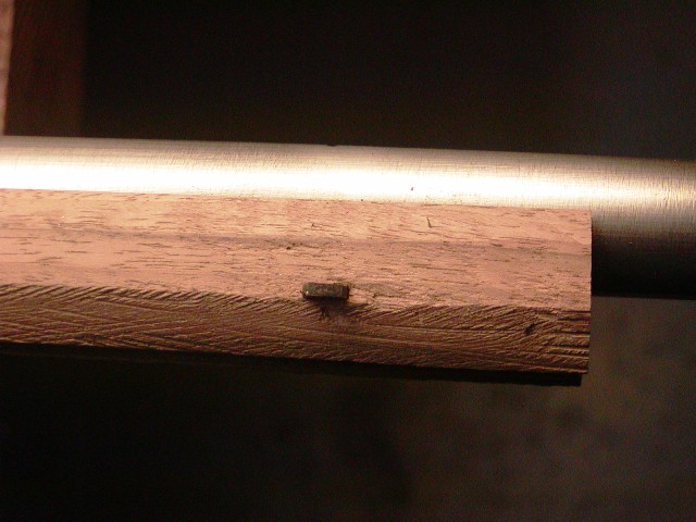
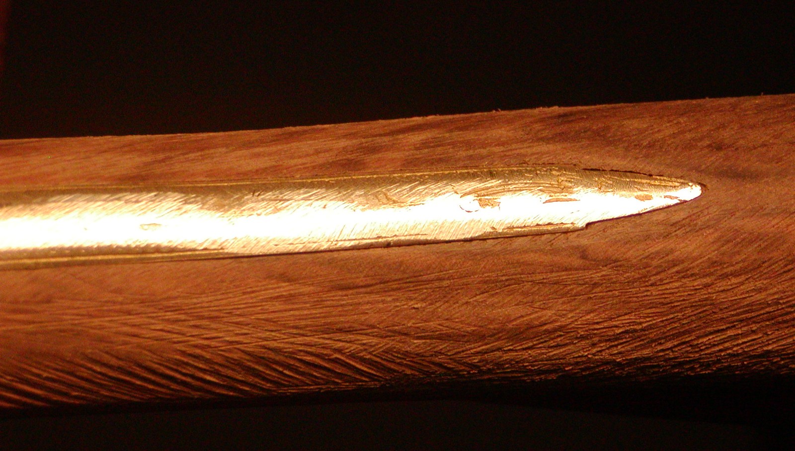
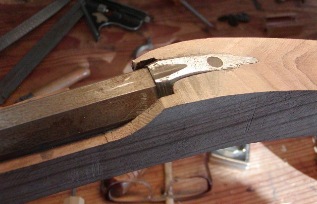
I fit the standing breech to the barrel then solder it in place. Then I inlet it into the stock attached to the barrel. The result looks like it grew from the wood. The breech has a sighting groove and hump, which will enhance the elegant profile of the gun. It should be a very elegant piece.
mREIYLl.jpg

OGAiyjg.jpg

RVJion3.jpg


dave
 
Well, I know what I'll be looking forward to when I open the forum for a while now. These topics are like a really good serial radio show that always leaves one eager for the next episode....
"Tune in next time for......"
 
Hi,

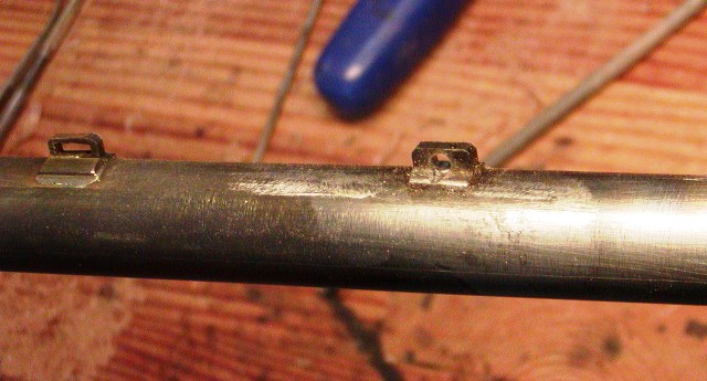
Got a bit done today. I made and attached the barrel loops for the keys. The rear loop is dove tailed into the octagon portion of the barrel and the forward loops are soldered to the round section of the barrel. I inlet them in the stock and then fitted the keys. If you look at my thread on making an 18th century English fowler, I show how keys are easily inlet.
GNbsGrS.jpg

I began shaping the fore stock with a plane and pattern maker's rasp. I always do that by forming facets that eventually get rounded. By doing that the shaping is even and I can establish the dominant profile easily and evenly.
QbCASvH.jpg

SLGRVtz.jpg

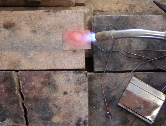
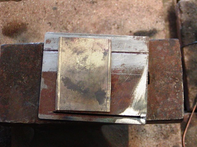
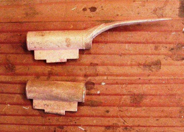
I began making the 3/8" diameter ramrod pipes. I use 0.0325" thick brass sheet, which is easy to cut with shears. After cutting out the rectangle, I anneal it by heating to red and quenching in water. That leaves the brass dead soft.
IwDaikk.jpg

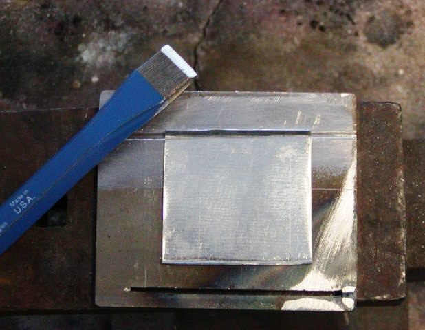
Then I form raised beading on each end using a little steel plate with a groove filed in it. I also use a cold chisel with the blade rounded to hammer in the bead. The plate and chisel work very well and makes forming beads, which also strengthens the pipe, very easy.
oJLkfdQ.jpg

aIIBlwn.jpg

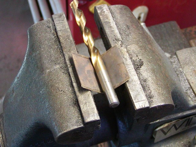
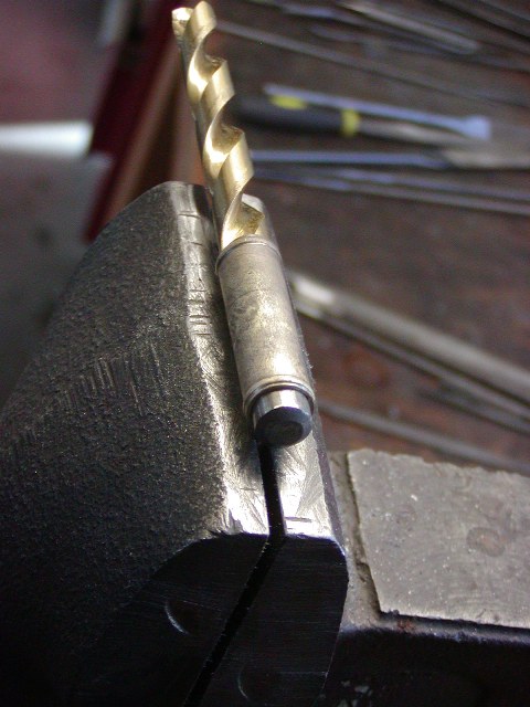
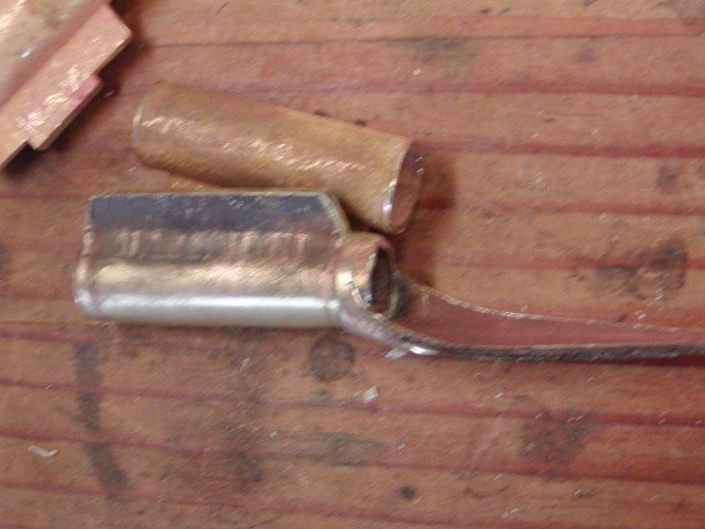
Then I wrap the sheet around a drill of the proper diameter. I usually bend it part way, then anneal the brass again, then pinch it closed in a vise.
7HLEqQF.jpg

Gqkspf3.jpg

GKlrra4.jpg

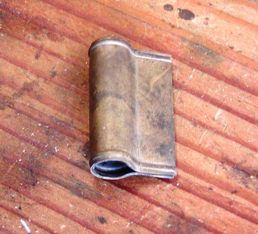
I run a bead of TIX solder in the tab to hold it together although that is not required. I have an original high end English fowler with silver mounts on which the sheet silver tabs are not soldered.
Next up is making the rear pipe and tang.


dave
 
Hi,

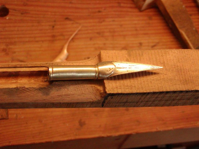
Not a lot to report today. I had a visit by a friend from Quebec and spent most of the day helping him with his "Little Fella's" rifle project for his daughter and designing a late flint era British hunting rifle for himself. I was able to make the rear ramrod pipe. My strategy for these English fowler rear pipes is to make the pipe from sheet metal and then solder on a cast tang. Based on the originals I own, that was how brass and silver rear pipes were made. The cast tang is thicker, making it less springy and easier to inlet, and you can file a terminal tooth or point in it that anchors the end of the tang in the wood. I won't need the tooth on this pipe but thicker metal allows me to shape it better. I buy cast rear pipes for fowlers from TOW or MBS and then cut off the tangs.
7M4gAwD.jpg

I make a sheet metal pipe that matches the forward pipes but it has a little more length or extension for the cast tang to be fitted. I fit the cast tang on to the pipe and solder it with Stay Bright or Hi-Force 44 silver bearing solder. On this gun I do not want a big step at the rear pipe. I want the tang for the pipe to be only slightly raised above the ramrod hole because I want the bottom of the stock to taper upwards from the trigger guard to the rear ramrod pipe. That sounds like a minor detail but it will make a huge difference in the profile of the gun and prevent the illusion of a bulge at the rear pipe, which happens if the bottom profile is parallel with the bore of the barrel.
o2rUp32.jpg

Here is the rear pipe almost ready for inletting. I will taper the tang more and shorten it a little. Here is the middle pipe ready for inletting.
HtdbbVg.jpg

vkLaumD.jpg

More coming,


dave
 
Hi,

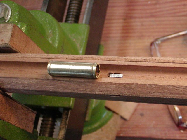
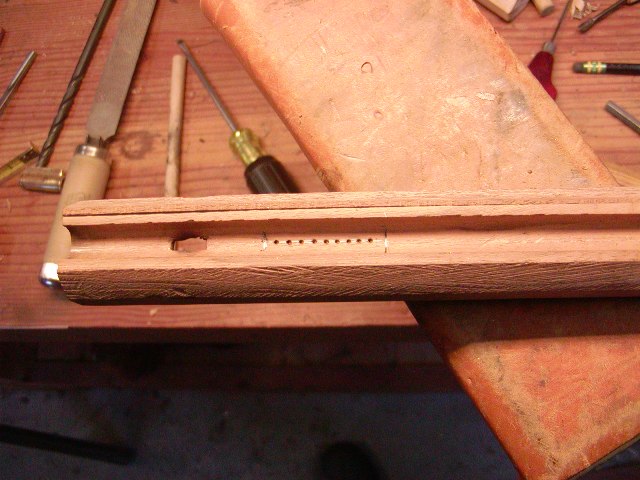
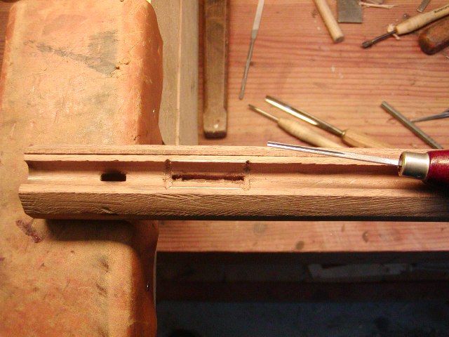
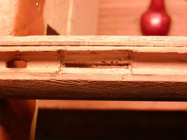
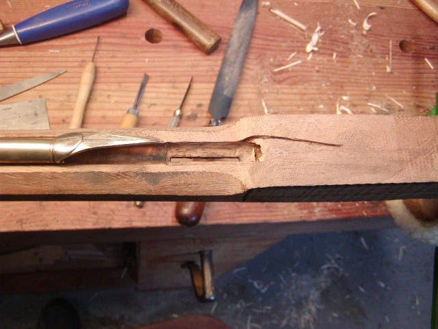
I inlet all the ramrod pipes today. First the forward pipes, I mark a line for the tab on the bottom of the ramrod groove and then punch a series of holes with an awl.
yfdkr9h.jpg

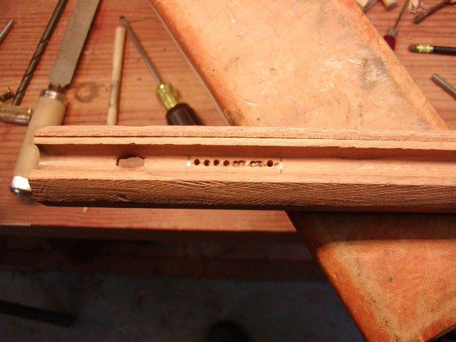
Then I drill out those holes a little narrower than the tab.
qRYDaPs.jpg

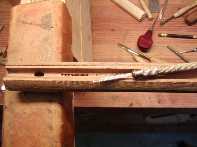
I cut out the wood between the holes with a broken fret saw blade ground to a narrow tip and mounted in a scalpel handle.
CtT3t8C.jpg

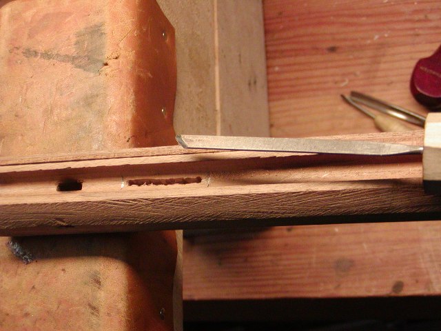
Next I clean up the slot with a needle file that has the end ground and sharpened as a skew chisel, It cuts away wood and then files it away.
FfyDAn9.jpg

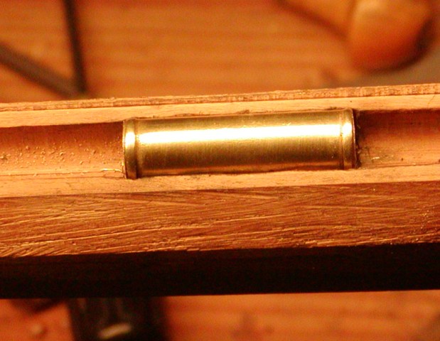
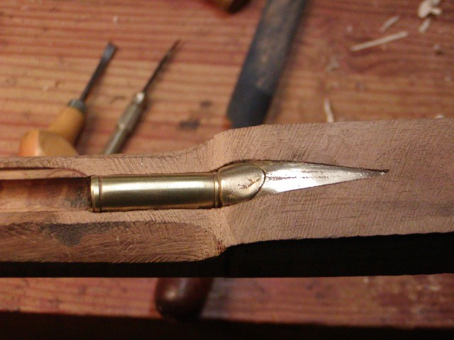
After cleaning up the slot, I insert the pipe and trace its outline on the wood. Using a tiny gouge, I cut the wood to receive the raised collars on either end.
2apvvGl.jpg

Then using inletting black and gouges, I cut the mortice until the pipe fits down in all the way.
WK20kXa.jpg

a686Gd6.jpg

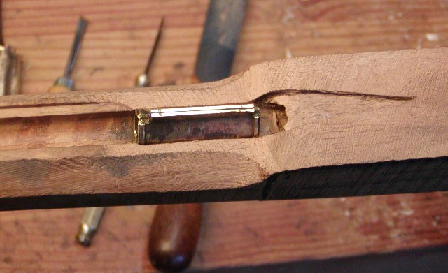
For the rear pipe and tang, I first cut and file away as much excess wood at the step as I can to reduce the amount of wood I have to inlet into. Then I use one of the other pipes, which are well matched in dimensions, to cut the mortice for the rear pipe.
QUkFtX7.jpg

. That makes it easier to insert the actual rear pipe in the mortice to outline and cut the tang. The pipes are all in and I will drill the holes for the pins a bit later.
11qLslb.jpg

EzEmrxs.jpg

dave
 
Hi,

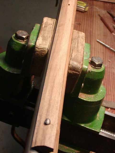
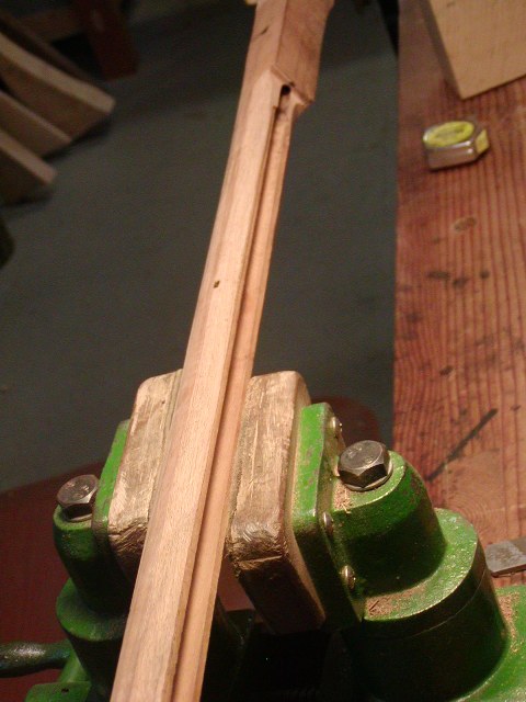
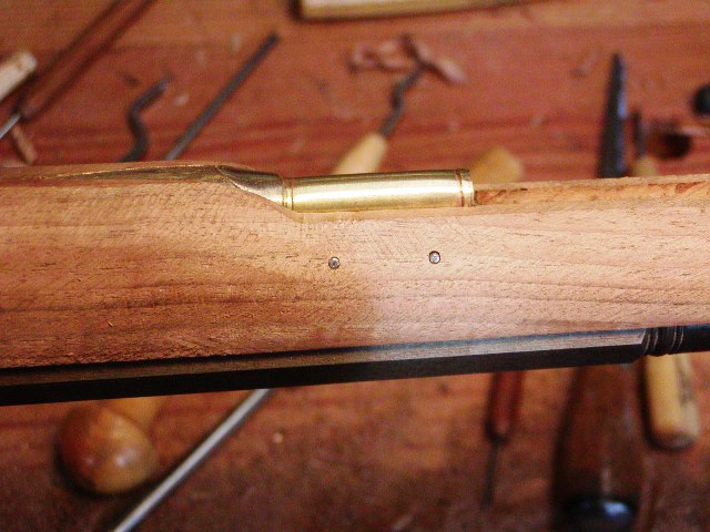
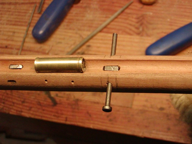
Drilled for the pins holding the ramrod pipes. I used 2 pins per pipe on this gun for extra security. When I drill the holes, I don't use any jigs. I simply make sure the edge of the ramrod channel is square and true along its length. Then I measure the depth of the ramrod channel from that edge. I mark that depth on the side of the stock and then draw a line or lines down from the ramrod channel edge to locate where I want the pin or pins to go. With an awl, I mark the hole or holes along that line but a little below the depth mark. I repeat that on the other side of the stock. Then I drill about halfway in from one side and again from the other. I can eye ball the drill to be level and perpendicular with the stock and it works great. After the holes are drilled, I insert the pipe and drill again to make the holes in the brass pipe. I use 5/64" pins and drills. They break far less often than 1/16" drills that many builders use.
NmAB6FF.jpg

VxJ2IGj.jpg

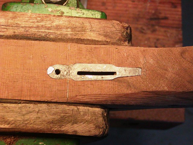
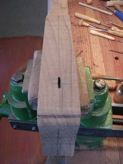
I drilled for the barrel tang bolt. I start by drilling a small hole in the center of the tang where the bolt will go and perpendicular to the surface of the tang at that point. You can use jigs and center punches to align the hole top and bottom but I find I can eye ball the drill and have it come out in the middle of the bottom. With an undersized hole, I can correct small misalignment with bigger drill or round file.
pZeBzwY.jpg

Then, I drill the hole the size needed for the tap, in this case a #21 drill for 10-32 threads. I enlarge the hole at the bottom to fit the round boss on the trigger plate that will be drilled and threaded for the bolt. I inlet the plate in the stock. For this plate, the rear is shaped like a chisel blade and cuts into the stock anchoring it in place. With the trigger plate in place, I again drill through the stock with the #21 drill. I remove the plate and drill again through the stock with a #8 drill for clearance of the bolt. I install the plate and using a 10-32 pulley tap, I thread the hole in the plate. This makes sure everything is lined up just right.

b7Bc88v.jpg

m2DJ1fE.jpg

BMHOlua.jpg

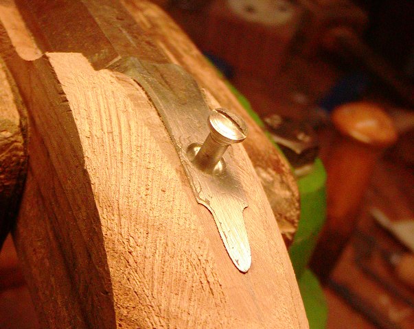
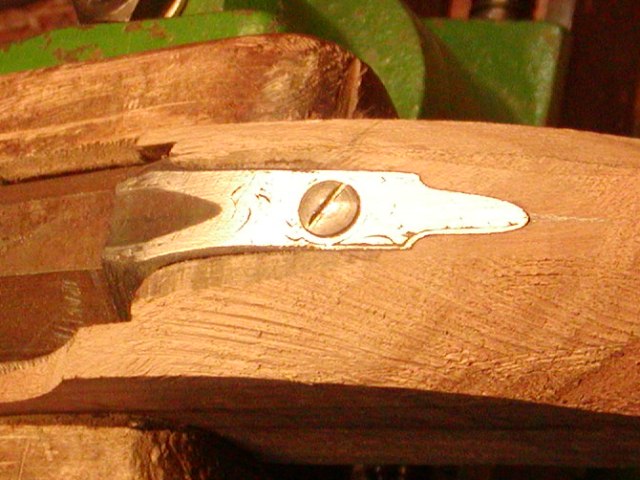
The hole in the tang is drilled part way through with a drill a little smaller than the diameter of the head of the bolt. I drill down just enough to create a squared shoulder in the hole. Then I use a 5/16" countersink to cut the bottom of the hole to the shape of the tapered bolt head. Finally, I turn a shoulder on the head of the bolt that fits into the hole. This is far superior to just counter sinking the hole and allows the head of the bolt to eventually be contoured nicely with the tang.
RLU9I80.jpg

sOyQCU8.jpg

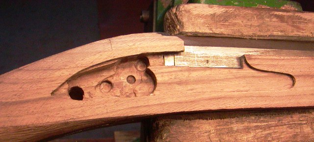
I inlet most of the lock guts except the mainspring. I neglected that spring simply because I just did not feel like doing it today. With the sear of the lock inlet, I could position the trigger. I want the trigger bar to hit the sear about halfway back from the trigger pivot pin. I cut and file the slot in the trigger plate accordingly, and then use it as a template for drilling a series of holes the length and depth of the trigger bar. Using a router bit in a Dremel destroyer tool, I rout out the holes for the trigger slot. It all takes just a few minutes.
Afm81od.jpg

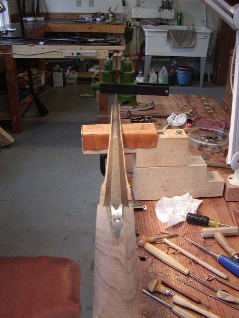
Finally, I trimmed off more wood from the fore stock and rounded it a bit. Much more will eventually come off. Then I also began shaping the wrist. That is where I am at the moment.
2Swco4Z.jpg

hVzZ7Fz.jpg


dave
 
Hi,

Major pivot today. I had to put the fusil aside to work on a Brown Bess for a while. During that time I mulled over the discussion we had on ALR about officer's fusils. Several really knowledgeable folks contributed and I began to rethink this project. What was I making, a sporting gun or an officer's fusil? I really respect Joe Puleo's opinions and I agree with his basic identifiers for a true officer's fusil, a full-sized bayonet mount and sling swivels. Much else could be up for grabs because there was no formal pattern, just what the private contractors were asked to make for their clients, which could include bulk orders of some standard design or a one-off gun of essentially sporting gun design adapted for military use. I think the beautiful fusil shown in the thread below is a good example of that.

https://americanlongrifles.org/forum/index.php?topic=46406.msg456207#msg456207
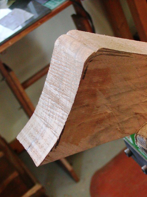
I decided against using the short bayonet and the butt plate with the trap door for it. Instead, I fitted a typical fowler butt plate from Jim Chambers and will mount a carbine-style bayonet and sling swivels on the gun. I inletted the butt plate. I've done so many of these my procedure is routine. I trim the stock with a band saw close to the profile of the butt plate and then rasp and file in a shoulder to begin fitting the tang.
3lF1kOP.jpg

These plates usually have a lug under the tang for a cross pin. The inlet for that lug does not have to be tight and it will need excess space forward so the butt plate can be moved forward during inletting.
M5cYPoQ.jpg

I always want a little curvature to the face of the plate and do not like those that are straight. Inletting that curvature is a little more challenging but if you use inletting black and go slow, it comes out fine. . The inletting came out well, nice and tight.
GkyH7vy.jpg

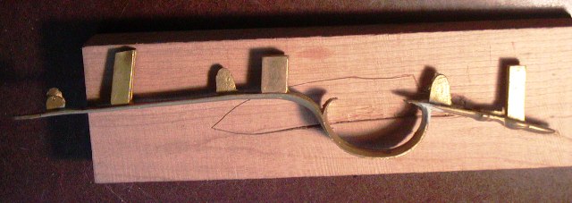
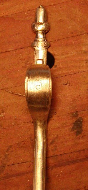
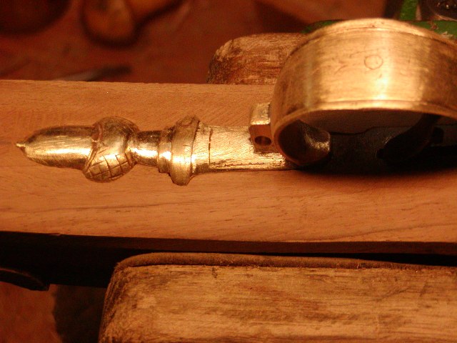
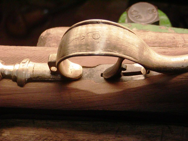
Next I had to deal with the trigger guard. I really like the design of the guard from TRS. The acorn is just right and the bow has the perfect "egg" shape and raised borders. But the casting had a serious flaw where the bow joined the front finial. The slightest pressure to bend the casting broke it.
FR6bkG4.jpg

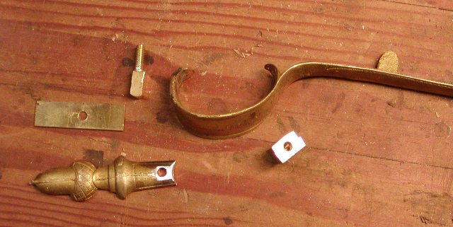
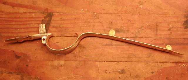
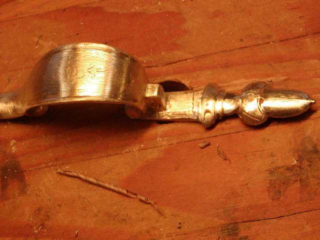
What to do. The commercially available castings from Track and others with the acorn finial are garbage. The skinny acorn is some misshapen design from who knows what and the bows are much too large. I can make a proper acorn guard from the urn guard sold by Chambers but I determined that I had an opportunity to use the TRS guard given that I wanted to mount a lug for a sling swivel. That gave me an idea. I created a group of parts to assemble the guard from its broken pieces. I made a boss for the swivel hole and gave it a threaded post that extends through the front final anchoring the forward lug on the inside of the guard. Then I cut brass sheet to make a spline connecting the finial to the broken bow.
8PVv8PV.jpg

I fitted that all together and soldered it in place using low temp silver bearing solder. Then I drilled and installed a brass rivet between the spline and the forward curl of the bow and another rivet between the upper part of the swivel boss and the trigger guard bow. After riveting, I heated all the solder joints to flow around the rivets and fill in any spaces. It worked. I now have a beautiful British fowler trigger guard complete with swivel boss much like the gun shown in the link above. The assembly should be very strong.
azygx0N.jpg

YsHXwuK.jpg

oBETQzZ.jpg


dave
 
Hi,

I got a lot done these past 2 days. I am having a lot of fun with this project. I prepared an inlet the trigger guard. I've written about this in previous post, but these long fowler guards are best inlet starting with the front finial. Inlet it fully and then clamp it in place before outlining the rear extension. For the rear extension, work back toward the rear inletting and fitting as you go. As the guard sinks into the inlet, it tends to move forward. Make sure the slots for the lugs can accommodate that forward movement. It is that shifting that causes a lot of inexperienced builders to end up with gaps at the end of the rear extension. Before inletting the rear extension, make sure the bottom of it is filed nice and flat and in most cases, thin it a bit. It does not need to have much thickness and the springiness caused by that mass will make inletting difficult particularly with cast steel guards. Another area many have trouble is inletting the guard down into the stock but running into the front of the trigger plate. Every guard and trigger plate combination is a little different but the problem can be addressed two-fold. File a step in the bottom of the forward curl of the trigger guard so it can be set lower on top of the trigger plate. Another trick is to inlet the forward part of the trigger plate so it is below the surface of the wood. Just make sure you file the wood flush with the rest of the plate beyond where the trigger guard overlaps. I usually do a combination of the two.

I had to deepen the inlet for the trigger plate to fit the guard and I also had to reduce the height of the trigger so it would fit within the bow of the guard. I like my triggers to have a nice graceful slant to the rear and barely sufficient clearance within the trigger guard bow. Note the "egg shape" to the bow. That maximizes clearance for your finger forward of the trigger without making the bow too big, something the Frenchies never learned.
7Cbi4Lt.jpg

GpM6Jny.jpg

NNk7PjG.jpg

After installing the trigger guard, I reshaped and pinned the trigger. The fusil will have a LOP of about 13 11/16ths ". The stock fits so well and the English "baluster wrist" architecture is really well designed. This rifle will be a real shooter. I shaped the butt stock a bit more and then removed and shaped the fore stock to the final dimensions. This will be a very slim gun. I will cut back the front of the stock a little more to fit a standard bayonet and also a brass muzzle band. In the end, this should be a very fine rifle. The flats around the lock will be about 1/3 the width they are now, maybe smaller.

dave
H0ag0VF.jpg

RurSFmj.jpg

7OguDYe.jpg

AbjKg5H.jpg

wxVaYUx.jpg

dKP46mk.jpg
 
Hi,

Lots of stuff got done in the shop today on several projects. I think listening to my favorite pandemic songs; John Prine's "Please Don't Bury Me" and Harry Nilsson's "I'd Rather Be Dead Than Wet My Bed" really helped motivate me. I added the swivel mount on the trigger guard, which means I need a fore stock swivel. Contrary to most reproduction Brown Besses, mainly by those who speak Italian, Japanese, and Hindi, the forward swivel should have a supporting lug on the barrel. I ran out of good lugs for round barrels and I like the loop to be at least 1/8" thick. I had to make it. I found a chunk of octagon barrel that I had sawed off and realized it would be ideal for the lug. The bore provides the curve of the base and there was enough thickness to make a lug tall enough and wide. A few hacksaw cuts and then a little filing was all it took.
eVy9KDv.jpg

3z0vizu.jpg

The forward swivel must always be located just in front of a ramrod pipe so the sling and swivel never block the ramrod channel. They lay against the pipe. I soldered on the lug and inlet it in the wood. Then drilled for the swivel pin.
jIMnJdF.jpg

c973iY8.jpg

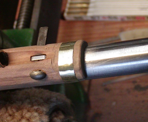
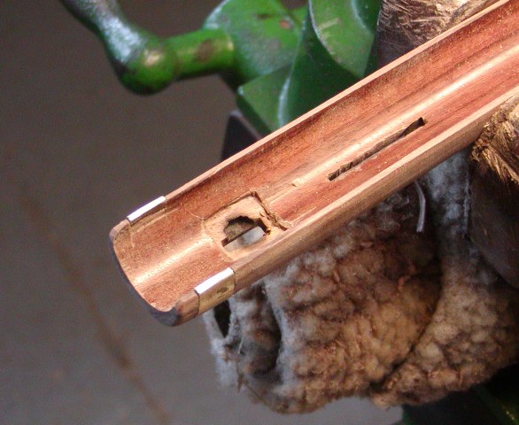
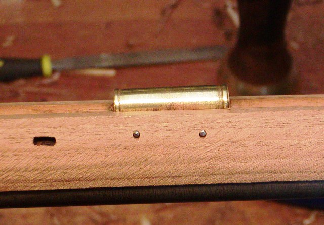
My next job was to make and install the sheet brass nose band. This gun does not have a muzzle cap, rather a simple band of thin brass sheet wrapped around the stock to reinforce the muzzle end of the stock. The band was made for 0.032" brass annealed brass sheet. I cut and file in the groove for the band in the stock, then make a paper pattern to measure the length of the brass sheet. Then I cut out the brass, bend over one end and attach it to the side of the stock. The soft brass bends easily around the mortice and I pinch the other side on to the stock with pliers. I will eventually rivet it with a brass rivet. It came out nicely.
Qak0u2R.jpg

IJ4PfhE.jpg

More to come.

dave
 
Hi,

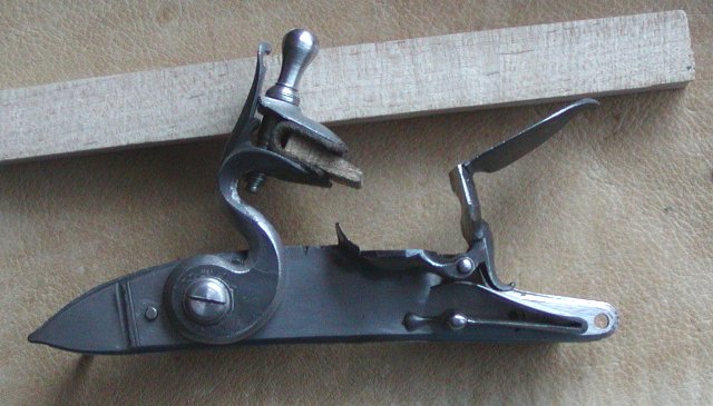
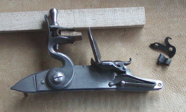
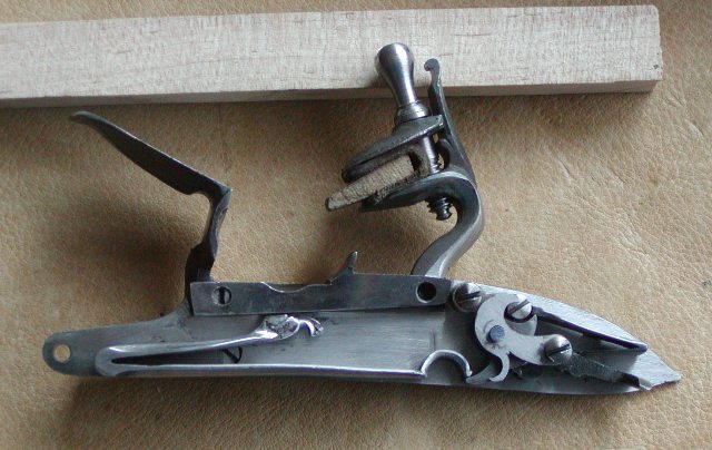
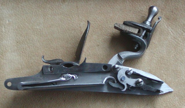
Well, more got done today. I resolved some lock issues. The lock is a series 569 from TRS copied from an original fusil by John Twigg made in the early 1770s. It had pretty good geometry, and the internals were nice but the flintcock did not work quite right. I don't think the square tumble hole in the cast part was positioned correctly. Anyway, I eventually found that the flintcock from a Chambers early Ketland lock worked. It just had to be trimmed a little smaller and some details added. I fitted it and in terms of geometry, it worked very well but it just was too massive and a little taller than fit the proportions of the lock as a whole. So, I went back to the original flintcock and filled the tumbler hole with weld and then cut a new one that positioned the cock better. It came out great. I had another problem. The cast tumbler bridle was very fragile. Likely because of some shrinkage during casting and then more loss of metal after cleaning up the cast part, it was not very robust. I hardened and tempered it but it eventually broke at a predictably weak spot. I ordered a replacement from TRS but that was long ago and with all that is going on, I decided to make a more robust replacement. I discovered that the bridle from an L&R Queen Anne lock would work well with a few minor changes. I have one of those locks, which I bought because it is the right sized round-raced lock for an early Peter Berry rifle I intend to build soon. However, after buying it I decided it needed too much work to be acceptable and decided I will use just the plate, flint cock, and frizzen (after filing off the stupid lug on the bottom of the pan cover) for the Berry but fill all the holes and install better internal parts and create a much better lock. As a result, I have some internal lock parts that can be salvaged for other projects. This is one of those. I just needed to weld over the sear screw hole and move it a little. I then filed the bridle to give it a nicer look but with a bit more excess metal for strength. It worked and is much stronger than the bridle that came with the parts set.
XZ7zLN8.jpg

NVBmGad.jpg

WB1GSbm.jpg

7ujOm7e.jpg

I will eventually polish, engrave and then case harden the lock plate, frizzen, and flintcock. The new bridle will also be hardened and tempered. I am also going to sole the frizzen with a hardened sheet of high carbon steel. The case hardened frizzen will produce abundant sparks but the face is very thin. That is likely the result of making a mold from a worn original and not compensating for that wear and then shrinkage. I want to add some mass to it so will attach a hardened sole.

More to come.

dave
 
Hi Guys,

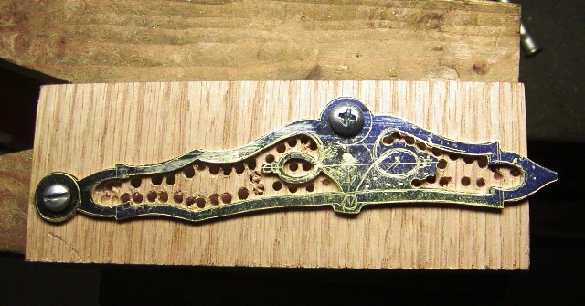
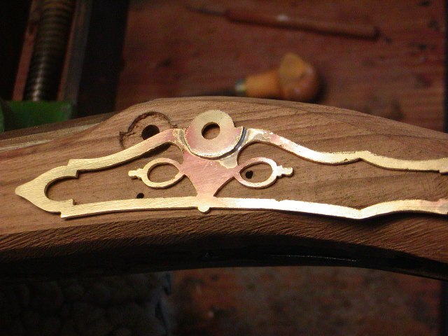
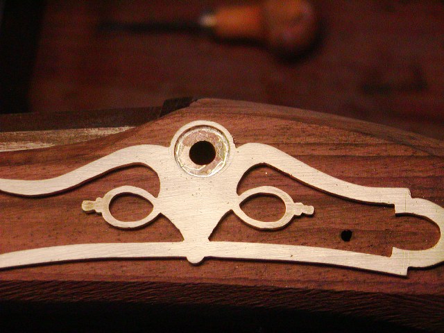
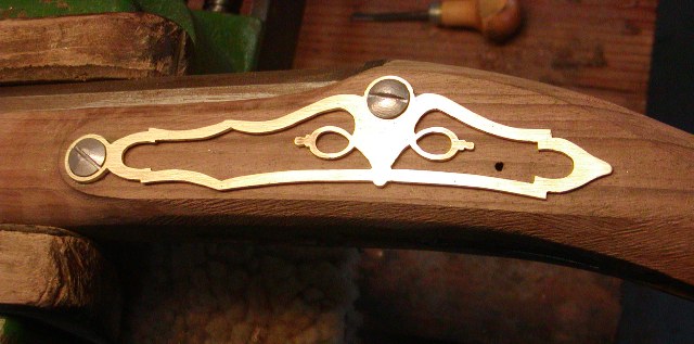
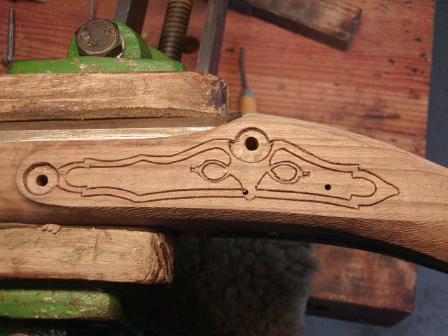
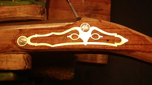
Spring cleanup and other projects including a Brown Bess diverted me away from the rifled officer's fusil. I needed to make a side plate and found a design that I liked in Neal's "Great British Gunmakers 1740-1790". It was the product of a provincial maker in Bristol, England but the open style was also used by Ketland and others. I modified the design to suit my decorative objectives and cut it out from sheet brass.
hQpBZII.jpg

. I filed it to shape and then created wells for the bolt heads by soldering brass sheet on the back. I've done this before and it is a slick way to avoid cutting the whole side plate from thick brass.
g8y0UO7.jpg

eprhMo9.jpg

GuaapWp.jpg

Next up was inletting it and it was no problem. The fact that so little wood has to be removed makes it go really fast especially when you have tiny chisels that fit the design. The solid area under the rear lock bolt will be engraved with the looped ropes forming the border of a shield. On the shield will be engraved a lion rampant or an armored bent arm holding a sword. Both are designs linked to honorable military service.
KbDwHmR.jpg

AQkxx2h.jpg

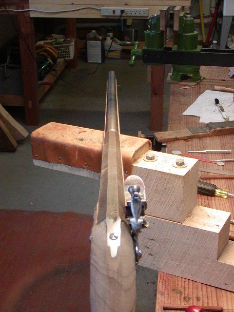
I trimmed the stock to almost final dimensions. I still need to final shape the lock and side plate panels and then final shape the stock. It will be ready for stain very soon but I have to checker the wrist first.
ua25QDu.jpg

Q11FN13.jpg

g44Be7M.jpg


dave
 
Hi,
It's been a while. I've had a lot of Spring chores to do and other gun projects. I also put the officer's fusil aside to consider my plan for decoration and prepare. I decided to be ambitious and consequently, I needed to plan and practice . I am fearless when it comes to growing my skills and experience, but I always have great anxiety when I decide to exercise that fearlessness. I worry about screwing up so I plan, practice, and then execute, always doing the best I can even if the result is flawed.

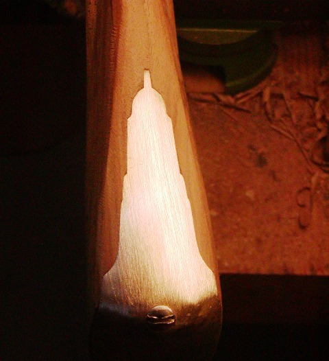
I finished detailed shaping of the stock and painted it with dilute stain made from black aniline dye dissolved in water. I then scraped off the black, which revealed all the scratches and tool marks. However, the black stain embeds in the open pores of the wood and will highlight the grain when I put finish on the gun. The next step was drawing the carving around the standing breech tang and cutting in the outline. I chose a rococo shell rolling in from one side as the motif. I love that design but haven't carved it in a while. After cutting and smoothing the background, I left cutting the details until later.

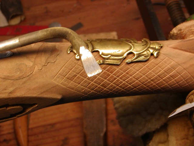
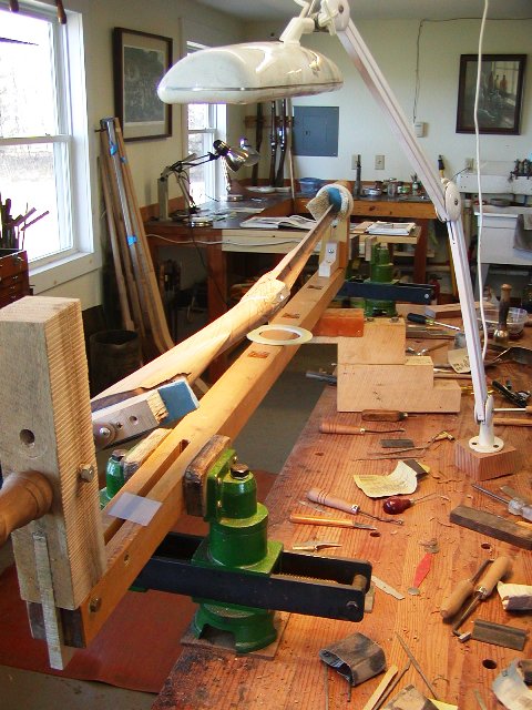
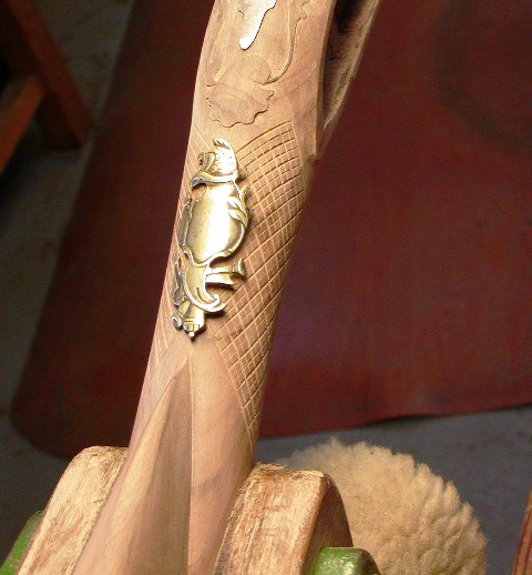
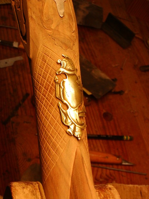
I wanted to checker the wrist in the coarse fashion used by British gun makers during the 1770s. The large diamonds are flat topped and the grooves look to be cut with a checkering saw and then filed with a checkering riffler.
I87fWMN.jpg

623Y5Dg.jpg

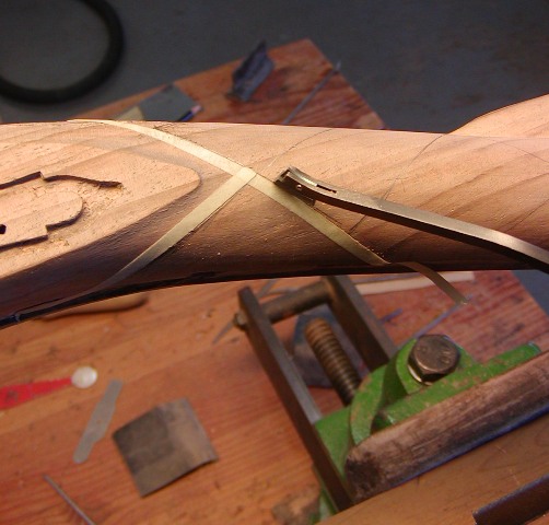
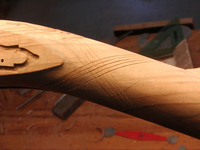
I made and used both tools to do the job. I marked guidelines using pin striping tape and a plastic "diamond" template that I made. I used a 60 degree single line cutter to cut those guidelines, then I used a 60 degree skip line cutter to make all the other lines.
3U12PGf.jpg

nz3ZiBX.jpg

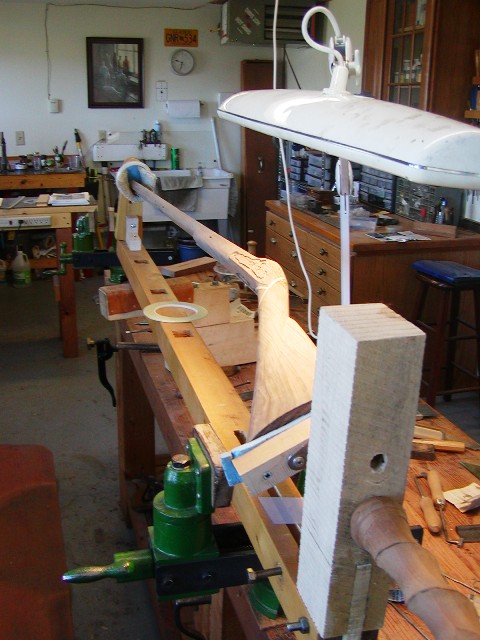
The spacing was 1/8" for the skip line tool. Then I deepened every other line with the checkering saw and the checkering riffler. That produced large diamonds 1/4" across divided into quadrants. Eventually, each quadrant will have a dot. It came out well although the lines do not match up perfectly side to side because the cast off in the stock makes the profile of one side of the wrist a little different from the other. The photos below show my checkering cradle.
m502nlt.jpg

qqJrqb6.jpg


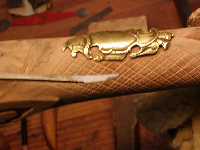
Next, I cast a copy of a thumb escutcheon from one of my original 18th century fowlers. After cleaning it up and chiseling details, I will inlet it on the wrist. I think it will be spectacular with the checkering. The photos show the original plate set in the stock but laying on the surface. It gives you an idea of what the final product will look like if I don't screw it up. These kinds of decoration are really sphincter puckering because you really can't fix them if you blow it.
HisD6Ec.jpg

1BZF92P.jpg


dave
 

Latest posts

Back
Top