Making a Rev War Period British Carbine

Muzzleloading Forum

Help Support Muzzleloading Forum:

This site may earn a commission from merchant affiliate links, including eBay, Amazon, and others.
Dave, it’s certainly captivating to read and see the technical skills you employ in these builds, but I also really enjoy the background history and idiosyncrasies you provide on the particular guns you build. It makes reading and following these a tutorials a much more interesting learning event.
Truly inspiring. Thank you Dave.
 
Hi,
I drilled the touch hole today. On these military guns that would never mount vent liners, I install Chamber's white lightning liners but made from carbon steel. They tarnish and disappear into the surrounding barrel. I drill the hole out to 5/64" diameter for these military guns. I use the liners as a safety measure. They increase the probability of ignition in all conditions substantially, and a misfire in a line of other reenactors is a safety issue. So I use the liners and was gratified that a few years ago at a reenactment of the British assault on Fort Carillon (Ticonderoga), on the French side after several volleys, only guns I built or worked over were still firing.

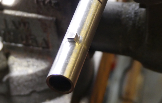
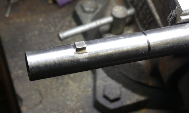
Today I mounted the front sight. The British always referred to it as the front sight not a bayonet lug. Repro military flintlocks usually just have the sight soldered on the barrel. TRS provides a little block of steel with a concave base milled in it to be soldered or brazed on the barrels. That is not how the originals were mounted. The sight with dovetailed base was installed in a very shallow dovetailed slot. It was then brazed or soldered. That is how I mount them using Stay Bright or Hi Force 44 low temperature silver bearing solder. I cut a very shallow (<1/16") dovetailed slot in the barrel. I use a cold chisel to hammer in the sharp corner of the dovetail on the barrel. Then I fit the sight with dovetailed base. After fitting it, I remove it and flux the barrel and sight base, and then solder in place. This creates a very strong attachment. After soldering, I file the base to be flush with the barrel.


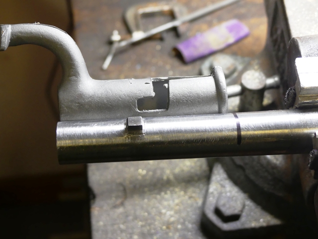
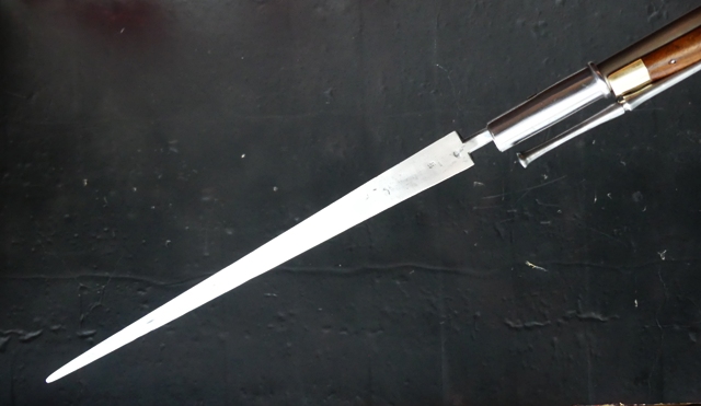
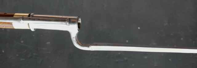
So how is the sight located so it also provides secure attachment for the bayonet? It must allow the bayonet to slide back far enough on the barrel so the barrel protrudes a little out the muzzle end of the socket yet the base does not butt against the nose cap of the stock. Some folks believe the socket needs to butt against the nose cap for support. This is rubbish. That is a recipe for a split stock. What needs to happen is the socket fits down snuggly on the tapered barrel (that is the real support) and the "Z" slot should position it and help to hold it snugly on the barrel. My shop fits bayonets as if the owners mean to really use them. They are going to stay on the gun even if driven into bone without pulling away. Of course, reenactors are not needing that security but they really like the fact that the bayonets don't fall off or rattle on their guns when marching downfield. Here is the cast bayonet for this gun provided by TRS. It will do fine. I show the socket against the barrel. You can see that a little barrel will protrude from the muzzle end of the socket and the base will not hit the nose cap. It is a tight fit. I addition, I will cut the end of the "Z" slot further up the socket and taper the slot so it snugs up on the sight. The owner will need to smack the bend of the bayonet with his palm to loosen it. That is how it should be.


Hi,
More work done. The lock is in and functioning properly.
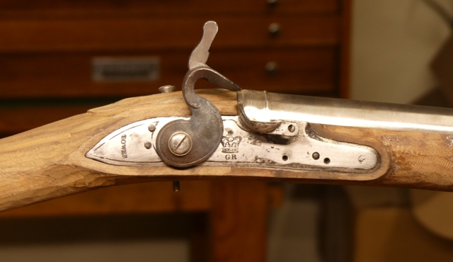


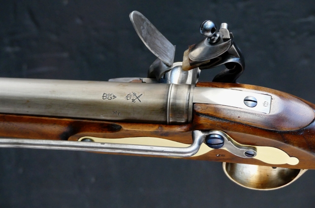
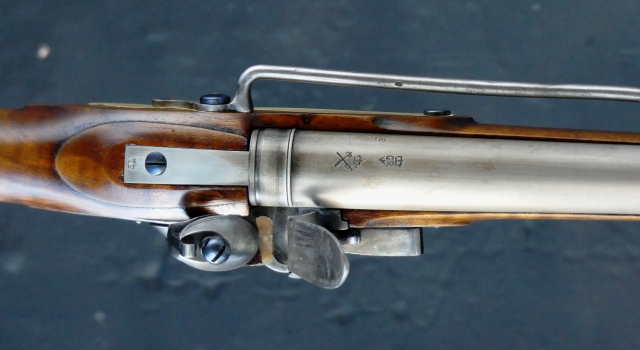
All of the cast in markings on the lock plate have to be removed and correct engraved marks added. The TRS lock has markings from the carbine pattern for 1799 and appropriate for wars against Napoleon not the American War for Independence. I also inlet the trigger plate and installed the tang bolt.
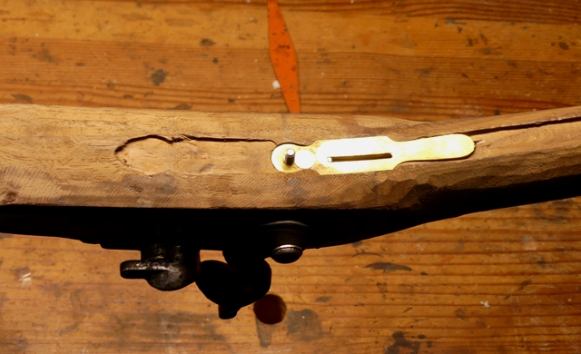


Note the slot in the plate is offset to the right bringing the trigger bar closer to the lock plate. The partial machine mortise was a little off center but not enough to really matter.

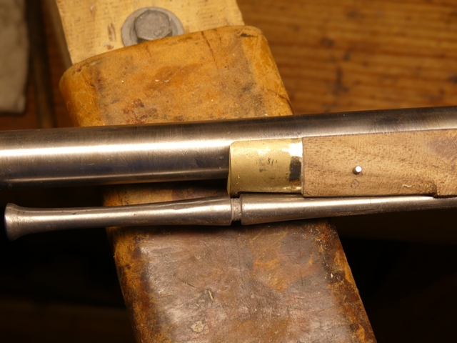
I inlet the ramrod pipes. They went in nicely and the tang of the rear pipe just needs to be filed flush with the stock.
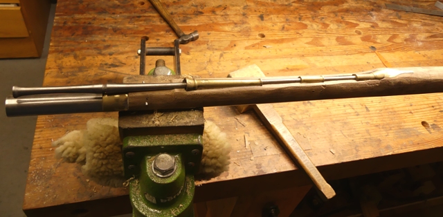
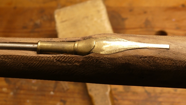


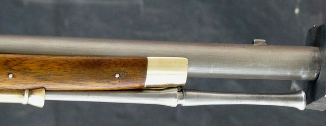
Normally, installing ramrod pipes is a trivial task but not on the Elliot and Royal Forester's carbines. The steel ramrod has a swell and cannelure (groove) that catches behind a lip on the front of the nose cap. Here is a photo of an original showing the ramrod and groove. The purpose was to make sure the ramrod did not fall out while the dragoon was bouncing along on horse back.
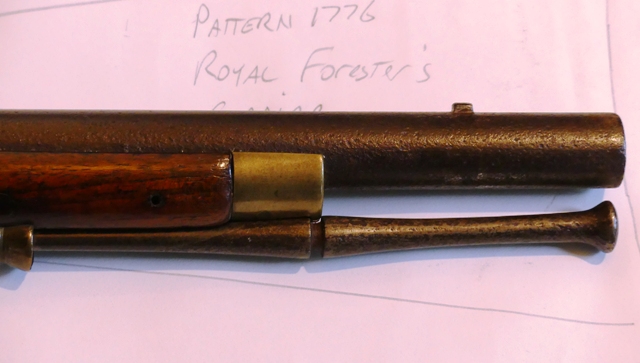


The TRS stock had a machined ramrod channel way too shallow for that system to work. The web of wood was too thick to allow the rod to butt up under the nose cap. I had to deepen it a lot. That presented me with a problem. I drilled the forward barrel pin hole nicely in the forward lug but not realizing how much deeper the ramrod groove had to go to make the catch system work. When I deepened the groove properly there was too little wood under the forward barrel pin to give it much strength. So I installed a new barrel lug and filled the hole I drilled. It will disappear when I am done. Then I drilled a new barrel pin hole higher up in the stock. I discovered that the position of all of the pipes effects how securely the locking mechanism works. It is not just a function of the front trumpet pipe. Every pipe has to work together to force the cannelure into the lip of the nose cap. It was very fiddley and required multiple adjustments in the depth of the pipes to get right, but I did.


More to come.

dave
Great tutorial! Thanks! Guys seem to just love Carbines! I'm afraid my method would involve a Sawz-All!:rolleyes:
 
Hi Folks,
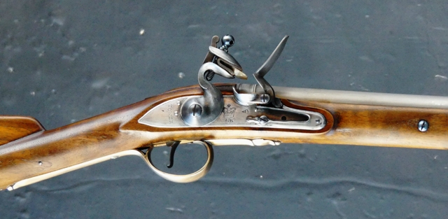
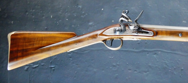
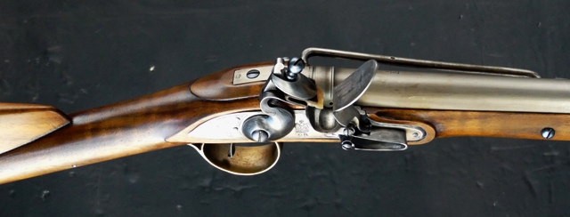
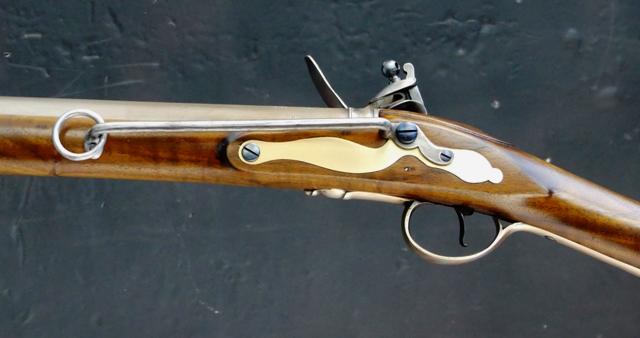
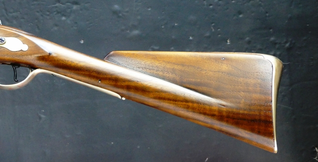
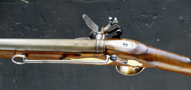
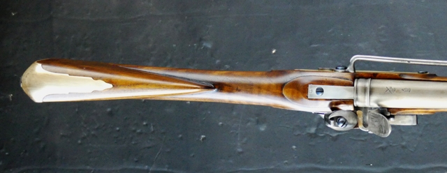
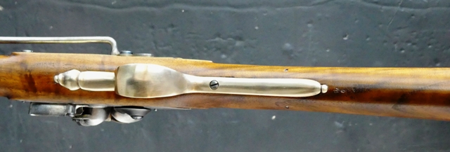
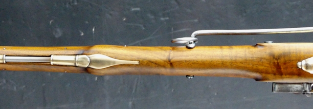
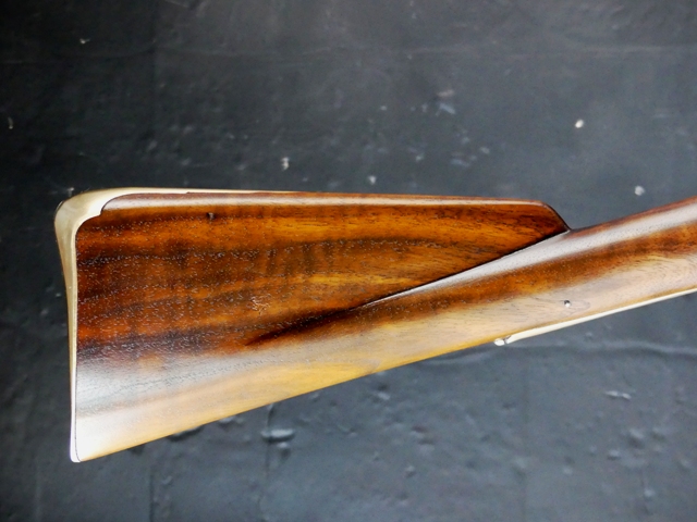
It is done. I had a bad bout with some sort of respiratory infection that stopped me from working but I am now over that. Maria is back from school and we just finished the carbine. Our end result is a plausible example of a pattern 1773 Eliott carbine that could have been issued to the 17th light dragoons serving in America during the Rev War. There is simply no clear documentary evidence identifying the patterns of dragoon carbines issued so every choice is based on circumstantial evidence or surviving examples thought to have Rev War provenance. We based our example on 2 surviving guns with early 1770s characteristics and thought to have been used in America. Consequently, if pattern 1773 Eliott carbines were issued to the 17th light dragoons in 1776, this is probably what they looked like.

Enjoy.


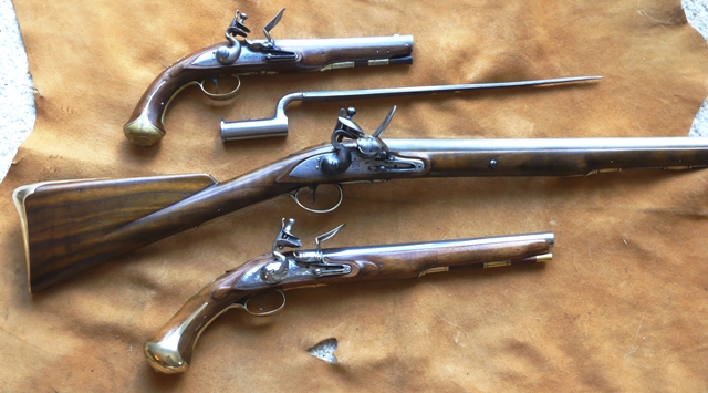
Here is a nice horseman's selection:


dave
 
Hi,
Thanks guys. The owner came by yesterday and picked up the carbine. He was over the moon. He will be using it a lot this next year starting with the Battle of Princeton. It is quite possibly the only accurate reproduction of a pattern 1773 Eliott in existence that could have been used early in the Rev War. Anyone building the carbine straight from the TRS parts set is not making a Rev War gun, rather one from a decade or two later.

dave
 
MR Person, yet again I remove my hat to you. I've been enthralled by the entire process that you have so graciously shared with us common mortals. Thanks.
 

Latest posts

Back
Top