• Friends, our 2nd Amendment rights are always under attack and the NRA has been a constant for decades in helping fight that fight.

    We have partnered with the NRA to offer you a discount on membership and Muzzleloading Forum gets a small percentage too of each membership, so you are supporting both the NRA and us.

    Use this link to sign up please; https://membership.nra.org/recruiters/join/XR045103

Snaphaunce Lock Build

Muzzleloading Forum

Help Support Muzzleloading Forum:

This site may earn a commission from merchant affiliate links, including eBay, Amazon, and others.

Erzulis boat

45 Cal.
Joined
Jul 14, 2005
Messages
566
Reaction score
78
Picture028.jpg


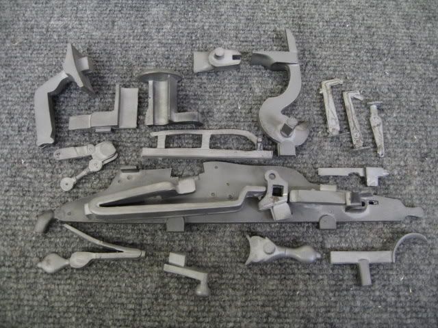
This is the snaphaunce lock casting set.

The casting quality is unbelievable. The parts are dead straight and 100% void free. Detail is superb.

The mechanics of the lock are very straightforward. The pan cover slides forward via a linear "ratchet" actuated by the ****.

The sear acts on the horizontal plane, and protrudes through the lockplate.

This particular snaphaunce also incorporates a secondary safety.

The lock is very large by modern (1700's) standards.

I will post photos as the "assembly" progresses.

I will have questions, and hopefully some answers.

This will be fun. :)
 
First step was to get the lockplate flat and "square".

I used a machinist's vise and an an arbor press to get the casting kinks out. This was after a simple initial draw filing. I merely removed the casting sprues and any grossly high spots.

You will never get it perfectly flat, but it should be as flat as you can get it within reason. With a straightedge, my plate was within .010" over the entire length, prior to drawfiling.

After the drawfiling, the .010" becomes .005" in a hurry. With the mechanical aspect of this lock, these figures could be tripled, and it would still function perfectly. Heck, the best L&R lock that ever left the factory is out 4 to 5 times this figure!

The backside however, has raised allocations for the primary and secondary sear, and the right angle shelf that the pan cover slides on, so a complete drawfiling is impossible. I did drawfile, but just enough to get a predictable flat surface. The indentations to indicate component location are plenty deep, and quite impossible to "erase".

So far so good.

I am now squaring up the remaining parts, but only enough to get the surfaces for critical interface squared away. For instance, the sliding pan cover is only cleaned up on the underside, and not to length, because the pan needs to be "sealed". I left the cover oversize to allow a great fit after the pan is installed. You have to resist the urge to get carried away.

Once again, this set from TRS is top notch. The **** pivot shaft is only "out of round" .001", and unlike the matchlock set, the shaft protrudes exactly 90 degrees from the backside of the ****.

Everything will go along great until it comes time to make the springs into springs, but that is why we have Roy on the forum.
 
Picture032.jpg


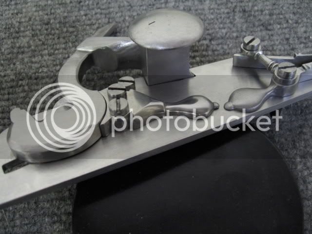
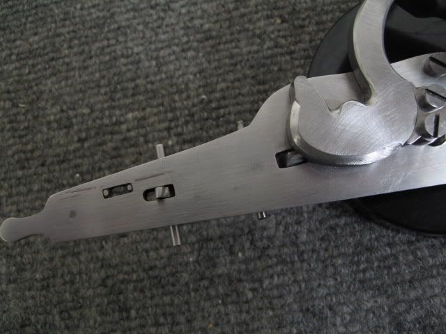
This is the ****, **** stop, and pan installed.

After "squaring" the lockplate, I installed the ****. This step is self explanatory, but due to the side pressure that the horizontally acting sear will put on the ****, a nice wobble free fit will ensure a very smooth action. If a lot of play is present, the flint strike will be inconsistent, and flint life would be greatly degraded.

The cockstop location is also somewhat critical. The mainspring is extremely powerful, and the **** travels forward with considerable force. The contact surface needs to distribute the impact across the curved face. The stop has a cylindrical protrusion forward of the 2 fasteners. I drilled the allocation for the protrusion, then mated the **** to cockstop surfaces evenly. I then applied forward pressure with the **** to anchor the stop, then drilled and tapped the 2 rearward fasteners.

The pan was squared to the lockplate interface on the mill prior to installation.
 
Picture035.jpg


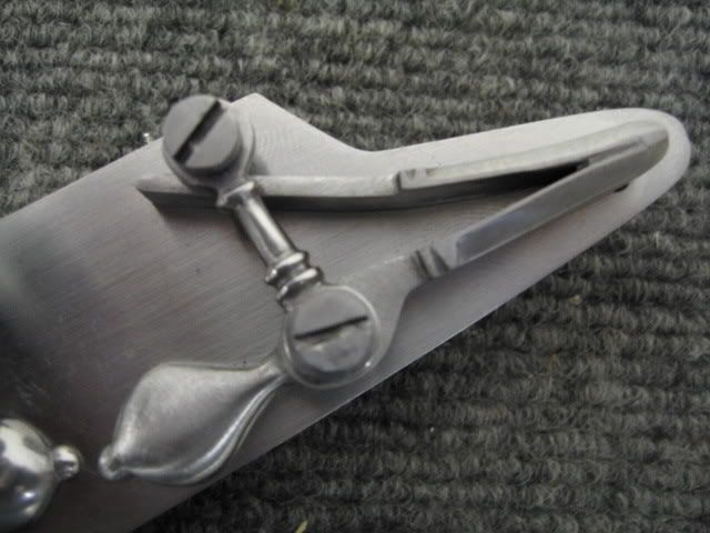
This is the spring for the "steel" (frizzen) installed.

The outer "link" that unitizes the frizzen spring and the frizzen allocation was drilled first. By drilling the "link" first, and locating from this component initially will ensure that the frizzen pivot bushing is not cocked to one side.

The frizzen will be installed last.
 
Picture033.jpg


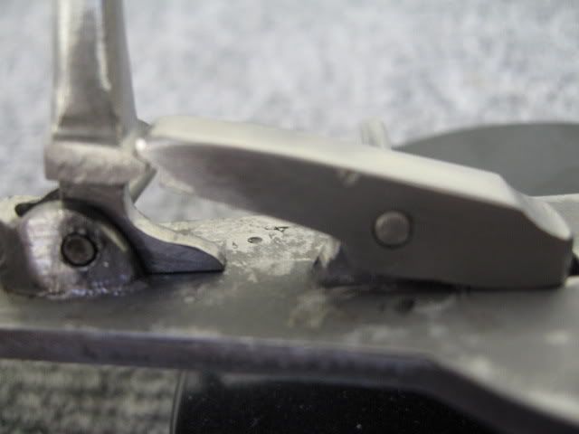
Here is the interface between the primary and secondary sear.

The design is great, as the trigger action is extremely smooth. The **** is held rearward by side pressure on an angled plane, not a 90 degree shelf. Once the secondary sear breaks away, the **** pushes it's corresponding sear nose out of the way. Smooth as glass.

The castings are superb, and there is plenty of metal to work with on the two sears.

Sear to sear contact is large and safe. The very nature of the design allows a solid contact. It is not supposed to have tiny contact surfaces like a more "modern" vertical acting sear.

If the interface is done properly, there will be no deviation in the **** engagement sear when the trigger is pressed, meaning.. the **** will show no signs of movement front to rear, or side to side, until both sear noses disengage.

I apologize for the blurred photo.
 
Picture034.jpg


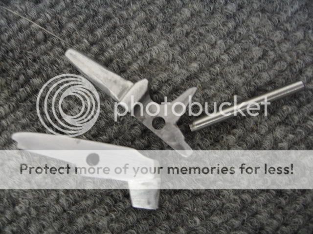
These are the two sears, primary and secondary.

The pin is pointing to the critical base surface that should be very uniformly flat to ensure a great feeling trigger. I also implemented a self contained overtravel feature.

Picture.jpg


This is how the sears should look from the outside of the lockplate. You must locate the two with enough room for the full range of travel.

I left the pins long so one can see the orientation.

The rearmost sear has an angled face that will mate with the safety yet to be installed.

The provided screws look out of place on this very old lock, as they are modern fillister head machine screws. You can modify them, or make your own to match the time period. I ended up just making my own like Roy does.
 
At this point, I am cleaning up all the spring castings in preparation of the next steps.


I will post more images after the weekend, as I should be able to squeeze in a few hours on Saturday.
 
So how is this project going?

Haven't seen the boat man post in a loooong time.

GoF
 
Great thread! This is one of the projects I want to tackle one day and I am learning a lot :hatsoff:
 
I must have missed something here? Who is the maker of these parts? Are they redily available? :confused:
 
The Rifle Shoppe...
If you are lucky you might get the parts in 90 days, if you are unlucky it might take 900! :)
 
Back
Top