Starting my winter pistol build early

Muzzleloading Forum

Help Support Muzzleloading Forum:

This site may earn a commission from merchant affiliate links, including eBay, Amazon, and others.
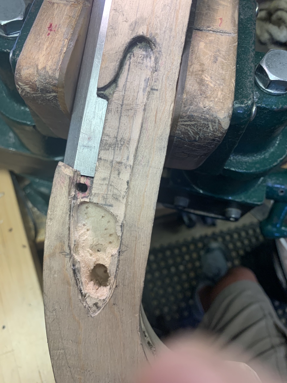
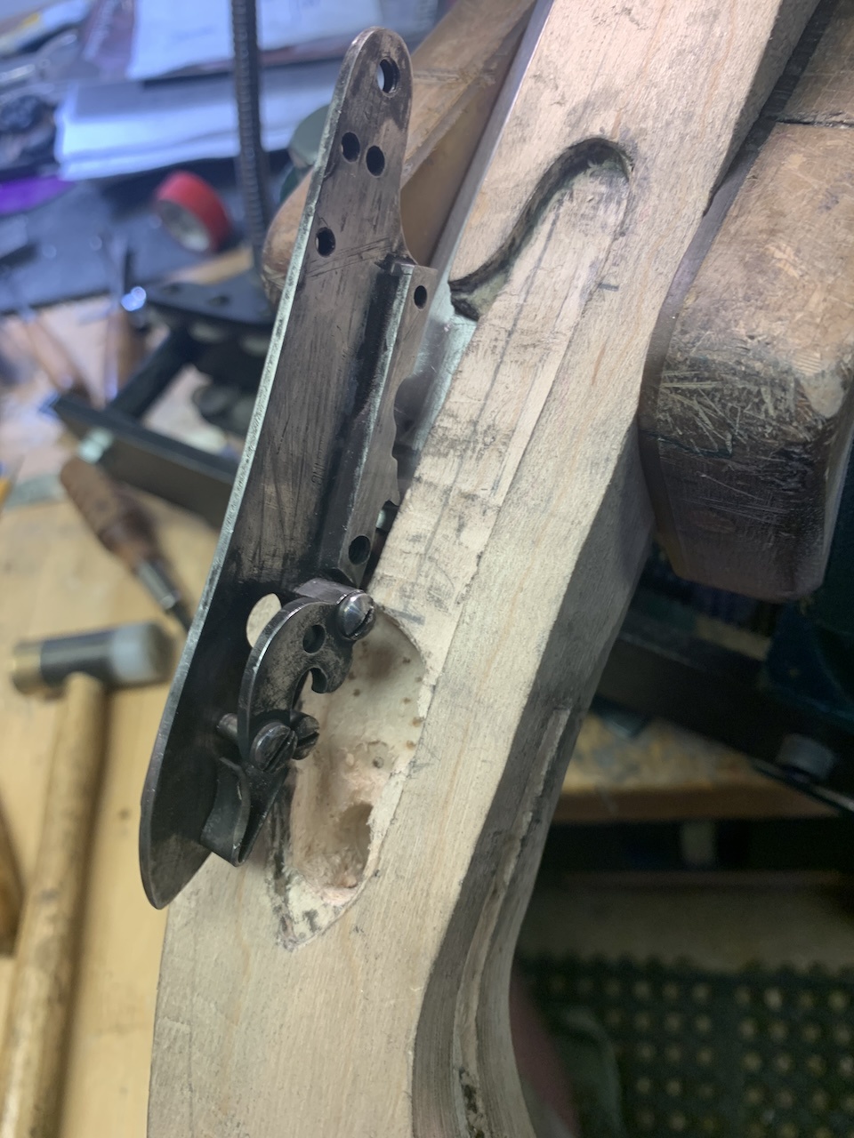
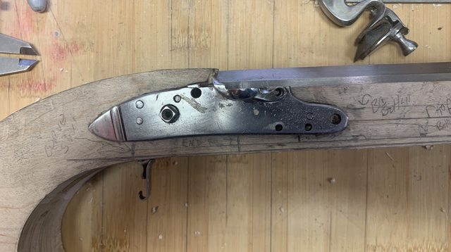
Maybe these pics will give you a better idea.
xj8iN4i.jpg
TiC3OPT.jpg
 
Maybe these pics will give you a better idea.

xj8iN4i.jpg
TiC3OPT.jpg
I’m no expert at building, and hope you don’t mistake my comments as criticism. It just appears to me that there is a lot of wood below the lock mortise. I was thinking that you would be removing a whole bunch there but see you already have your trigger plate inlet. I could be way wrong but I am thinking that this pistol will be really chunky.
 
You need no more than an ⅛ “ below the ramrod. Do that before the trigger plate, or when you inlet the entry pipe, you’ll be way out of line. This will keep the bottom of the stock even and flat.
IMG_1232.jpeg
 
I’m no expert at building, and hope you don’t mistake my comments as criticism. It just appears to me that there is a lot of wood below the lock mortise. I was thinking that you would be removing a whole bunch there but see you already have your trigger plate inlet. I could be way wrong but I am thinking that this pistol will be really chunky.
Well....I have the measurements of 1/8"....and I even had 'em marked on the stock. But I squared up the stock a bit more before inletting the TP.....and then I forgot to take off more wood.

I went out last night to double check it....and sure enough, I have more fat to trim. I'd likely have caught this when I take the step to shape the grip.....but I'm glad you brought this to my attention!!

You're not making me do more work....you made me look at the work that "I forgot" to do in the first place!!

Thanks!!
 
Well you certainly appear to have good building skills . But remember what they say, “look to the originals”.
This is an original Hallbach and Son flintlock (circa 1780-1820, Baltimore).
Notice that the bottom of the pistol is not “flat”. It actually recesses upwards and narrows from the rear entry pipe right back through to the rear of the trigger guard. Where it doesn’t need to be as thick. He’s removed as much as possible there. Look carefully and see that lower section is actually a flowing “s” shaped curve, from the bottom of the grip swell up and through the rear entry pipe. Had he kept a straight line, this gracefully proportioned pistol would look like a real clunker!
This pistol is really, really comfortable to hold.
 

Attachments

  • IMG_3053.jpeg
    IMG_3053.jpeg
    3.9 MB
Last edited:
Pathfinder,
That is a perfect example of what NOT to do. Obviously, not all the builders of old were great craftsmen. Looks like he was “making do” with parts that weren’t the best choices.
Look at Manton, or Nock, you’ll never see anything like that.
Sorry, off the soap box now.
 
Pathfinder,
That is a perfect example of what NOT to do. Obviously, not all the builders of old were great craftsmen. Looks like he was “making do” with parts that weren’t the best choices.
Look at Manton, or Nock, you’ll never see anything like that.
Sorry, off the soap box now.
Thanks for your input on my providing such a bad example of Early American historical pistol building. Halback and Son had built a few hundred pistols in their/his shop. Another member here has a brace of almost identical ones.
Some of his pistols are valued in the thousands of dollars, and interestingly, one was featured in The Antiques Road Show.
Now, about that soapbox 🤔
 
Last edited:
Fixed it.....

GHSkVBKl.jpg


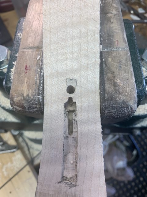
My TP measures .110 thick. The following pic shows I had to come down another .110 to make it skinny and meet the .125" lower than the bottom of the RR hole. This pic below is the bottom of the pistol after I took the wood down to the proper height. On the plus side, I consider the first inlet of the TP to be "just practice". :ghostly:

nLmlzP0l.jpg
 
Methinks you have building experience a'plenty. I'm impressed. Will the finished product be for you, for sale, for a gift?
Thank you for your very kind words. I haven't built a lot, only 3 rifles and one pistol.....and hours and hours of reading build books and on line research. I'm still very much an amateur.

This will be just a target pistol for me. Here in PA to hunt deer with a pistol the minimum caliber is 50. My other pistol is 50 and I built it just for deer hunting. I've missed two doe with that pistol.....not the pistol's fault. I have a 54 cal Leman build that I just love to hunt with, so the pistol takes a back seat.
 
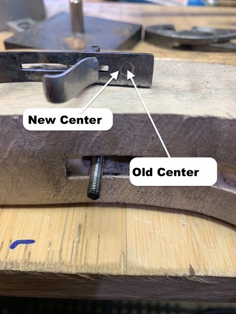
Well, since I made my mistake of not taking the bottom wood down to the right distance, after I corrected that.... my trigger plate hole is off. Because the tang bolt is at a slight angle, when I removed another .150 of wood, the proper hole location needed changed. I tried a few work arounds, but the bottom line is if I want it to be right, and not look like I Jerry-Rigged it, the trigger plate hole needed moved.

So, today I silver soldered up the existing hole and will drill\tap a new one. That way when the tang bolt is screwed in it will be at a 90-degree angle to the tang itself.

Lots of mistakes can compound themselves if it's not done right the first time. Fortunately this was an easy fix. And I have just enough metal so the new location will not break into the trigger slot. (I measured that!!)

A6mtw58l.jpg
 
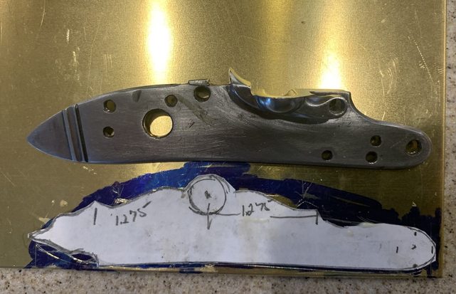
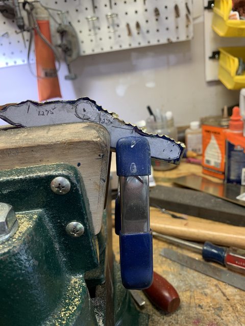
Began working on the side plate. .800 thick brass sheet. Cut out the pattern on paper, glued it to the sheet brass, drilled a bunch of holes around the pattern, then hack sawed through the web. Lots of filing still yet to do, but it will get there.

bFL1C0ul.jpg
9ndfA6Dl.jpg
xRRBaRKl.jpg
 
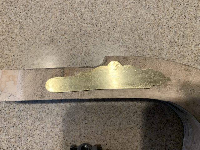
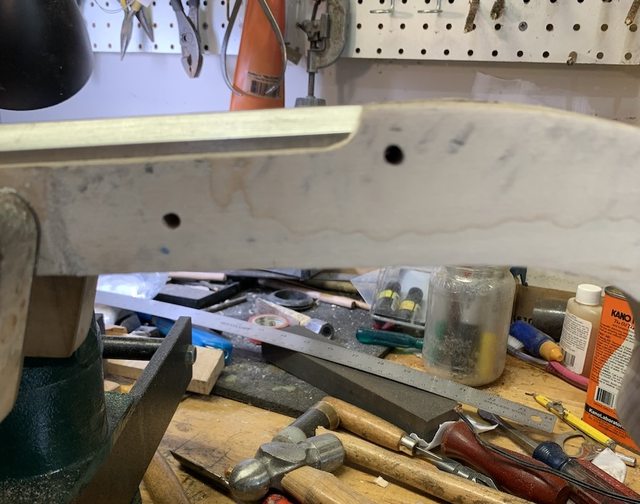
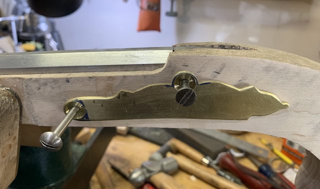
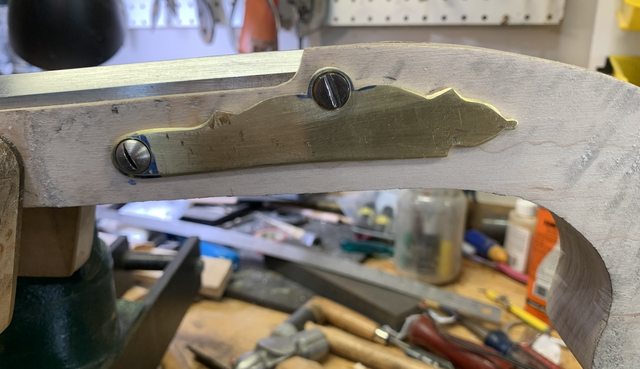
So, today was spent (and spent I am) final shaping the lock plate, then doing the critical (critical to me) drilling of the lock plate holes and mounting to the pistol. Remember, this lock plate started out as a piece of sheet brass.

Now, this came out great (for me) and I still need to do a little more shaping of the brass around the screws so the brass around the screws is the same. Then once I have that worked out I will finish the outside bevel (some edges are already beveled) then I'll inlet it into the stock. (BTW...these are not the final screws in the lock. These are just "working screws" as they get put in and removed so often they get pretty beat up)

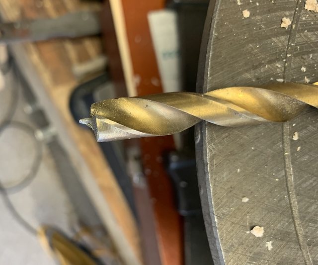
I wanted to recess the screw heads on the side plate as I think that looks really cool. But....that's a process that took the time today. This was my first attempt at doing a recessed bolt head. First, I had to take a drill bit and grind\sharpen the tip so it would drill a nice flat recess into the brass. (Last pic) The process for drilling is to first use a center drill bit, followed by this flat drill bit, and finally the size drill that will open up the hole so the bolt will fit. And the holes in the brass side plate must align with the holes already drilled\tapped in the lock plate that's on the other side. I swear I measured those distances 100 times.

I wasn't sure I was going to use the front bolt hole or not. But at this point, considering the work that's involved in silver soldering and filing out the front bolt hole, I decided to just drill for a front bolt. Lots of double checking before drilling so the bolt hole will miss breaking out into the barrel channel as well as the ramrod channel. (Gotta go through the web) I did fine as the drill went where I wanted.

hNeWbiul.jpg
hfN0Cv4l.jpg
7fBuzO4l.jpg
QTxXJNEl.jpg
 
You started this posting Aug. 13 and I just found it.

What an enjoyable read. The candid information and the great pictures to follow along with, this is so great. Thank you so much for your posting and I hope you get your deer so this project can continue.
 
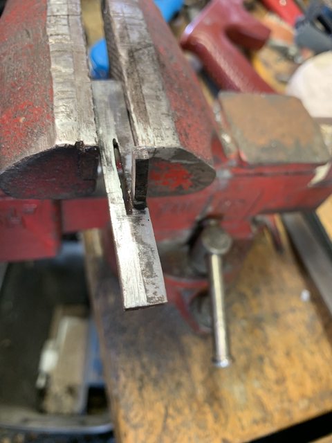
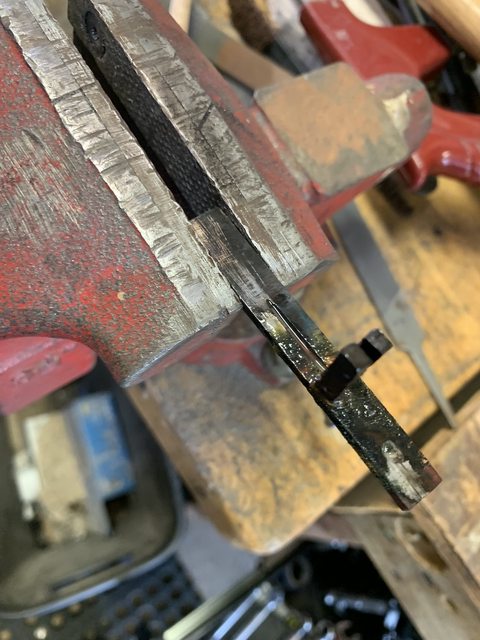
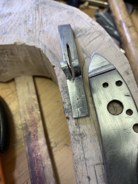
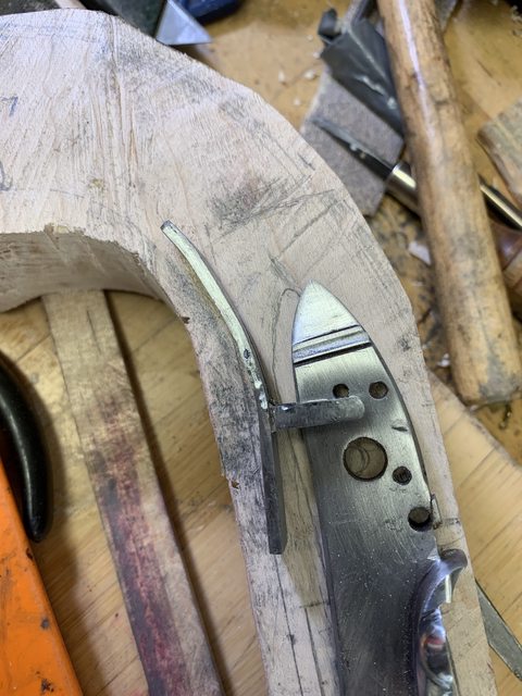
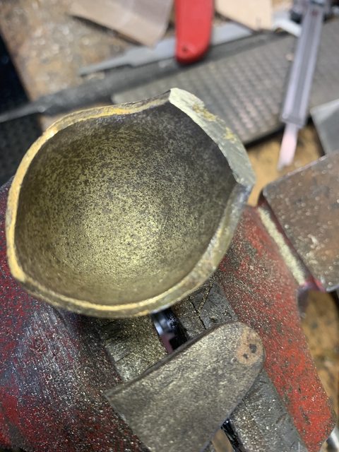
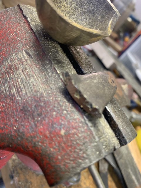
Welp....always some setbacks. At times they can be small setbacks, and at times not so small. I'd say this one was between small and the middle.

I'm installing a buttcap on this pistol and the one I have is cast. I was planning on "beating" one out of sheet brass, but this one came along on a great deal.

I needed the tang of the cap to bend towards the middle just a bit more to get the profile I wanted. I annealed it. And didn't hit it hard, but on the second hit (again, not hard) SNAP!!

I just needed a little bit more of the tab closer to the center in order to match the contour of the grip. I want the buttcap to tilt slightly up from the rear. I didn't need much movement of the tab.....but I certainly got more than I wanted!

I'm going to blame it on casting voids. (What? My fault?) Maybe you can tell from the pics....but these pics I already began to file the break. I think I can get the angle right silver soldering it back together. I need to square up the break...that will lose maybe 150-thousands on the length, but that's not much.

I thought I'd file a small bevel on each broken piece, fill it with SS, as I will attempt to make it look like that silver solder joint look like that silver line is suppose to be there.

This may work out OK.....this may end up being one in the trash and a learning curve.

DcwInEgl.jpg
3V35wX2l.jpg
 

Latest posts

Back
Top